
Building an automated watering system is conceptually simple:
- Build a network of pipes that brings water to plants,
- Use a microcontroller controlling solenoid valve to start or stop the flow of water,
- Activate watering at predefined times through the microcontroller (e.g. once every 2 days for 20 minutes).
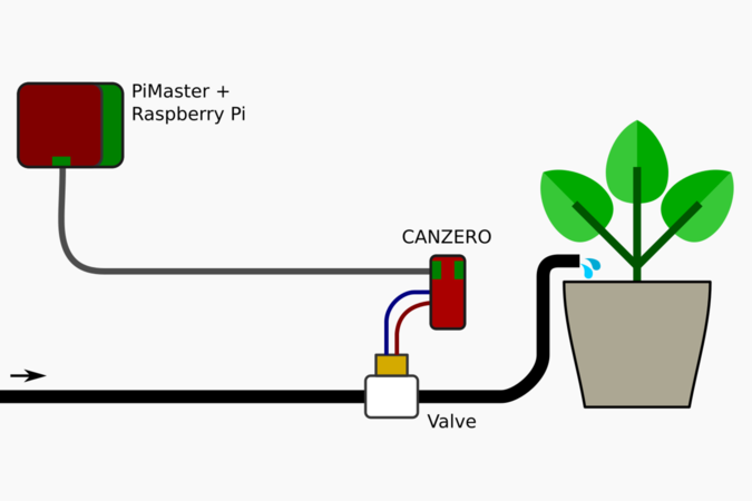
We'll look at building an automated watering system with the Omzlo NoCAN IoT platform, which is based on a set of Arduino-compatible nodes managed by a Raspberry Pi. Our general setup is shown in the figure above:
- An Arduino-compatible CANZERO node is connected to a valve, which is switched and off to water the plants.
- The CANZERO node is connected to a Raspberry-Pi with a cable both for power and networking.
- The Raspberry-Pi (fitted with a PiMaster HAT) is used to send instructions to the CANZERO, for automated and manual watering.
To keep things simple, we will limit the features described in this project. But it's easy to build on this example to add support for controlling watering with a smartphone or through the MQTT protocol.
Hardware
Basics
There are plenty of types of water valves, using various voltages, latching or non-latching, adapted to different topologies, etc. One of the simplest water valves is the 12V plastic 13mm (1/2") solenoid valve pictured below and that you can find for cheap on Adafruit or on eBay.
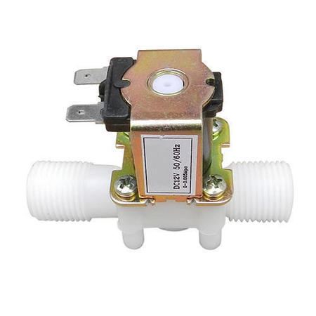
That valve is "normally closed" and when there is no current applied to the solenoid, the valve simply closes stopping the flow of water. It requires a minimum water pressure to operate (0.02 Mpa): without that pressure, the valve won't close well. As such, these valves are not bi-directional: they expect water to flow in a specific direction as noted with an arrow on the plastic body of the valve. While it is rated for 12V, it operates without issue at 9V or even below. A current of 200mA to 300mA is necessary to keep the valve open, letting water flow through.
One of the simplest ways to control this solenoid valve is with a low side (N-channel) Mosfet switch, as illustrated in the figure below.
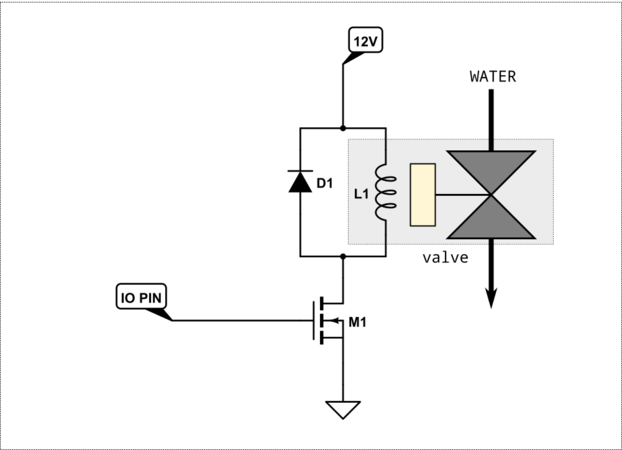
A microcontroller IO pin is used to control the Mosfet M1. When a sufficient voltage is applied to the gate of M1 current flows through the solenoid and opens the valve. Conversely, when the gate voltage goes down to 0, the Mosfet stops allowing current to flow through, thereby closing the solenoid.
The selected Mosfet should be "logic-level compatible" so that the 3.3V volt provided by a microcontroller is enough to fully turn on the Mosfet.
As always with an inductive load like a solenoid, a "flyback diode" D1 is added to protect the circuit from voltage spikes.
In addition, a weak pull-down resistor (not shown) should be placed between the gate of M1 and GND. This assures that the gate of the M1 is at a predefined state when the micro-controller is not powered on or defective.
A final point to consider is that a 12V power source must supply current to the solenoid.
Using a CANZERO node
Our goal is to control our watering system with a CANZERO node in a NoCAN network, allowing us later to program it directly from the command line on a Raspberry-Pi or through a web interface.
NoCAN networks use a single cable to connect a series of nodes together. The cable brings both power and networking (CANbus). A NoCAN network can use any voltage between 6 to 28V, but using 12V or 24V is a classic approach. Since we can build a NoCAN network with 12V, we can make an interesting simplification here: we can power both the solenoid and the network nodes with the same source, simplifying our cabling by avoiding an extra 12V power supply and cable for the solenoid. Note that if your NoCAN network uses long cables with small wires, then the activation of the solenoid will generate current and result in a minor voltage drop due to the resistance of the wire. In most settings, this is not a problem.
With this in mind, the low-side Mosfet switching circuit described above is very easy to build on a breadboard or even on a prototype shield that can be connected to a CANZERO node.
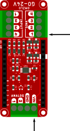
But we are lazy and there is an even simpler solution: using the Omzlo GO-24V shield which is an Arduino MKR compatible shield that is designed to interface a microcontroller with 24V systems (and of course 12V systems). It is pictured below, sitting on top of a classic Arduino MKR-Zero.
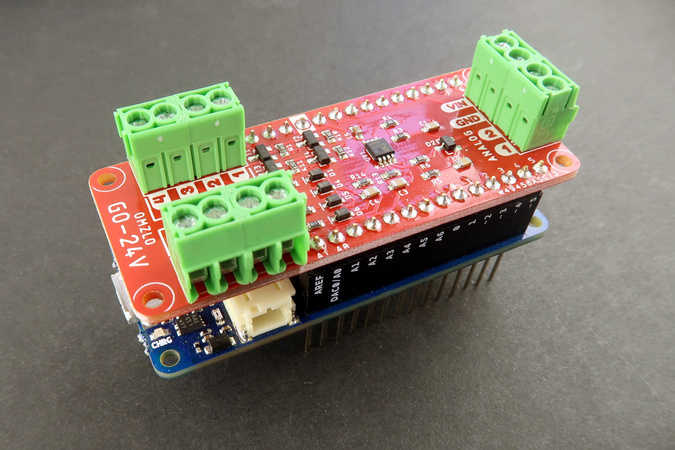
The GO-24V shield has notably 4 Mosfet controlled sinking outputs, exactly like in the low-side switch we described above.
We connect the VIN header (12V) on the shield to one connector of the valve and we connect the other connector of the valve to the first sinking output of the shield, both identified with an arrow in the figure below.
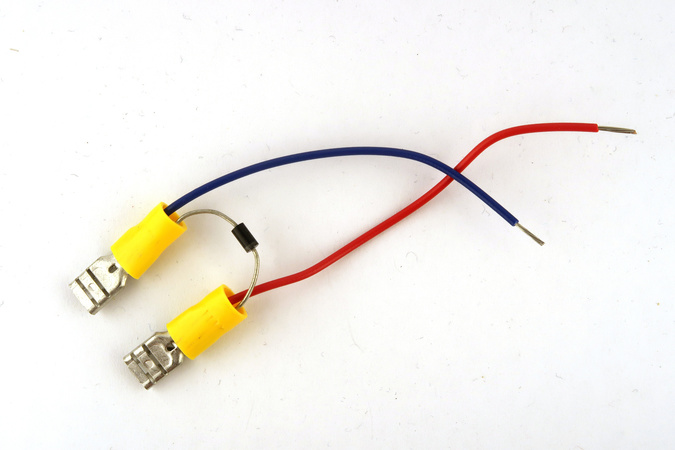
We only need to add the flyback diode and we are done. One simple way to do this is to build the following cable, designed on one side to connect to the shield through terminal blocks and on the other side to the solenoid with female disconnect crimp terminals that fit the solenoid, integrating a 1N4007 diode. The cathode of the diode should be connected to the 12V side, the anode to GND.
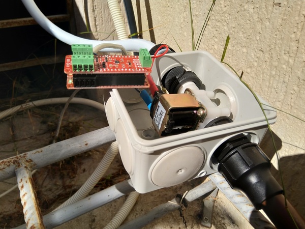
The valve, the CANZERO, and the GO-24 shield can then all be placed in a box and connected to the NoCAN network as well as the water pipes.
Software
Arduino sketch
We will create two channels to control our watering system on the CANZERO node:
- A channel called "watering/valve": sending "1" (or "open") to the channel opens the valve while sending "0" (or "close") closes the valve.
- A channel called "watering/timer": sending a numeric string greater than 0 to that channel will open the valve for the corresponding duration in seconds.
In addition, these channels will have the following properties:
- Sending "0" to "watering/valve" channel will cancel any ongoing watering timer.
- If a timer is set, the CANZERO node will update the channel "watering/timer" with the remaining watering time every 10 seconds, providing feedback to the user.
The gate of the Mosfet controlling the solenoid will be connected to the CANZERO/Arduino pin 0. We will also use the Arduino RTC library for timing purposes, taking advantage of the 32.768K crystal oscillation of the CANZERO.
This provides us the following sketch.
#include <nocan.h>
#include <RTCZero.h>

#define SOLENOID_PIN 0

NocanChannelId valve_cid;
NocanChannelId timer_cid;
uint32_t start, duration, last;
RTCZero rtc;

String msg_to_string(NocanMessage &msg)
{
  // nocan messages are always <= 64 bytes long
  char buf[65];

  for (int i=0; i<msg.data_len; i++)
  {
    buf[i] = msg.data[i];
  }
  buf[msg.data_len]=0;
  return String(buf);
}

void open_valve()
{
  digitalWrite(SOLENOID_PIN, HIGH);
  Nocan.led(true);
}

void close_valve()
{
  Nocan.led(false);
  digitalWrite(SOLENOID_PIN, LOW);
  if (duration>0)
    Nocan.publishMessage(timer_cid, "0");
  duration = 0;
}

void setup() {
  // Init the RTC
  rtc.begin();

  Nocan.open();
  Nocan.registerChannel("watering/valve", &valve_cid);
  Nocan.subscribeChannel(valve_cid);

  Nocan.registerChannel("watering/timer", &timer_cid);
  Nocan.subscribeChannel(timer_cid);

  pinMode(SOLENOID_PIN, OUTPUT);

  close_valve();
}


void loop() {
  // put your main code here, to run repeatedly:
  NocanMessage msg;

  if (Nocan.receivePending())
  {
    Nocan.receiveMessage(&msg);

    if (msg.channel_id == valve_cid)
    {
      String valve_str = msg_to_string(msg);

      if (valve_str == String("close") || valve_str == String("0"))
      {
        close_valve();
      }

      if (valve_str == String("open") || valve_str == String("1"))
      {
        open_valve();
      }
    }

    if (msg.channel_id == timer_cid)
    {
      String duration_str = msg_to_string(msg);

      duration = duration_str.toInt();

      if (duration>0) {
        last = start = rtc.getEpoch();
        open_valve();
        Nocan.publishMessage(valve_cid, "1");
      }
    }
  }


  if (duration>0)
  {
    uint32_t now = rtc.getEpoch();

    if (now-start>=duration) {
        close_valve();
        Nocan.publishMessage(valve_cid, "0");
    } else {
      if (last!=now && (duration-now+start)%10==0)
      {
        Nocan.publishMessage(timer_cid, String(duration-now+start,DEC).c_str());
        last = now;
      }
    }
  }

  delay(100);
}
With the latest version of the Arduino IDE, uploading the sketch to the node is easy: simply select the right node in the Tools/Port submenu and click on the "upload" button.
For more details on uploading sketches see the relevant section in our big tutorial.
Testing
Our system can be tested either with the web interface or from the command line.
On the command line, using nocanc running on the Raspberry-Pi NoCAN gateway:
- typing nocanc publish "watering/valve" 1 should open the valve.
- typing nocanc publish "watering/valve" 0 should close the valve.
- typing nocanc publish "watering/valve" 0 should close the valve.
We can also use the builtin web user interface to control the watering system. Log on the Raspberry Pi gateway and launch the web UI, for example with the following command:
nocanc webui --web-server=":8080"
Assuming, as an example, that the Raspberry Pi gateway has the address 192.168.0.32, you can then point a browser to http://192.168.0.32:8080, where you will find a screen similar to the following:
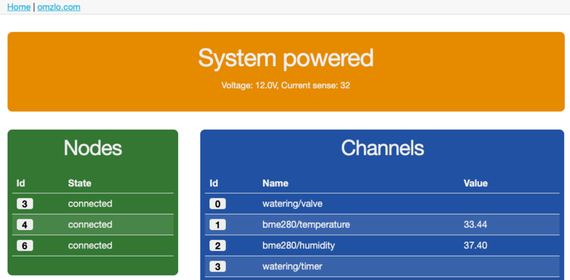
Clicking on the channels numbered 0 ("watering/valve") or 3 ("watering/timer") allows controlling the watering system the same way we can do it on the command line.
Notes: our own setup has many channels, including a set of temperature/humidity/pressure channels based on a BME280 sensor.
Scheduling watering
The NoCAN network is controlled by a Raspberry Pi computer fitted with a PiMaster HAT. This is the perfect location to automate your watering system schedule with just a single line of code!
Linux systems, such as the Raspbian distribution that runs many Raspberry Pi machines, offer a very simple tool to schedule tasks on a regular basis: cron.
The Raspberry-Pi website already provides a nice and quick tutorial on cron so we won't go into details here.
Assuming that the nocanc tool has been installed in the /usr/local/bin/nocanc directory and that the watering timer is controlled by the channel named watering/timer, we can program a 10 minute watering session every day at 8:00 AM, using the following entry created with crontab -e:
0 8 * * * /usr/local/bin/nocanc publish "watering/timer" 600
Going further
Adding more nodes
What happens if we have several nodes each controlling one (or more) valve(s)? Each node would need to create channels with a different name to distinguish the different valves, e.g. "watering1/valve", "watering2/valve", etc. This would mean that we need to write a slightly different version of our sketch for each node, changing the name of the channels in each sketch.
Luckily there is a little trick we can use to simplify our life: if we insert the string $(ID) in a channel name used in NoCAN, that portion of the channel name will be replaced by the actual node id of the CANZERO node creating the channel. As such, in our sketch, we can replace the following line:
Nocan.registerChannel("watering/valve", &valve_cid);
with:
Nocan.registerChannel("watering/$(ID)/valve", &valve_cid);
If the node creating the channel is node number '6', then the created channel will be watering/6/valve. If 3 different nodes run the same sketch they will, therefore, create 3 channels, each with a different name based on their node identifier. Node identifiers remain constant across restarts of the nocand server, so, for example, we can use the channel watering/6/valve in our crontab script as it will not change.
We would proceed similarly for the channel watering/timer which would be replaced by watering/$(ID)/timer
We only need to write one Arduino sketch and we can deploy it on as many nodes as needed!
Final thoughts
To keep things simple, this blog entry provided just a basic but functional watering system based on the NoCAN IoT platform. It's easy to extend it by adding a nice web interface to control and schedule watering operations. You can also connect this system to blynk in order to control plant watering with a smartphone, even if you are far away from your garden!
As a next step, we will try to add a capacitive soil moisture sensor to schedule watering based on the soil humidity. But this is for another blog entry!
To stay updated on the NoCAN project, don't forget to follow us on Twitter or on our Facebook page.
Comments
Good morning,
My name is Tomás Campos, and I am part of the non-profit organization HUMANIZED TECHNOLOGY (https://TECNOLOGIAHUMANIZADA.com).
We would like to invite you to publish an article about the use of the NoCAN IoT platform to water your plants in the garden. Of course, the invitation is at no cost.
For the past fourteen years, we have been dedicated to supporting the "street family," empowering this socially disadvantaged group in the central area of Buenos Aires, Argentina. We provide responsible support based on horizontal and intrafamily relationships, daily interaction, and close coexistence. Additionally, to address the need to highlight the irresponsible use of technology, especially in its social aspects, we started the HUMANIZED TECHNOLOGY Magazine. Unconscious use of technology leads to marginalization and deprives marginalized sectors of options.
We are also running the social empowerment project Empowered Reality (https://RealidadEmpoderada.com), which aims to create a 3D platform for raising awareness about responsible social practices.
Would you be interested?
We look forward to your contact via email.
Tomas Campos, almost 2 years agoGood morning,
My name is Tomás Campos, and I am part of the non-profit organization HUMANIZED TECHNOLOGY.
We would like to invite you to publish an article about the use of the NoCAN IoT platform to water your plants in the garden. Of course, the invitation is at no cost.
For the past fourteen years, we have been dedicated to supporting the "street family," empowering this socially disadvantaged group in the central area of Buenos Aires, Argentina. We provide responsible support based on horizontal and intrafamily relationships, daily interaction, and close coexistence. Additionally, to address the need to highlight the irresponsible use of technology, especially in its social aspects, we started the HUMANIZED TECHNOLOGY Magazine. Unconscious use of technology leads to marginalization and deprives marginalized sectors of options.
We are also running the social empowerment project Empowered Reality, which aims to create a 3D platform for raising awareness about responsible social practices.
Would you be interested?
We look forward to your contact via email.
Tomas Campos, almost 2 years agoGood morning,
My name is Tomas Campos, and I am part of the non-profit organization HUMANIZED TECHNOLOGY.
We would like to invite you to publish an article about the use of the NoCAN IoT platform to water your plants in the garden. Of course, the invitation is at no cost.
For the past fourteen years, we have been dedicated to supporting the "street family," empowering this socially disadvantaged group in the central area of Buenos Aires, Argentina. We provide responsible support based on horizontal and intrafamily relationships, daily interaction, and close coexistence. Additionally, to address the need to highlight the irresponsible use of technology, especially in its social aspects, we started the HUMANIZED TECHNOLOGY Magazine. Unconscious use of technology leads to marginalization and deprives marginalized sectors of options.
We are also running the social empowerment project Empowered Reality, which aims to create a 3D platform for raising awareness about responsible social practices.
Would you be interested?
We look forward to your contact via email.
Tomas Campos, almost 2 years agoGood morning,
My name is Tomas Campos, and I am part of the non-profit organization HUMANIZED TECHNOLOGY.
We would like to invite you to publish an article about the use of the NoCAN IoT platform to water your plants in the garden. Of course, the invitation is at no cost.
For the past fourteen years, we have been dedicated to supporting the "street family," empowering this socially disadvantaged group in the central area of Buenos Aires, Argentina. We provide responsible support based on horizontal and intrafamily relationships, daily interaction, and close coexistence. Additionally, to address the need to highlight the irresponsible use of technology, especially in its social aspects, we started the HUMANIZED TECHNOLOGY Magazine. Unconscious use of technology leads to marginalization and deprives marginalized sectors of options.
We are also running the social empowerment project Empowered Reality, which aims to create a 3D platform for raising awareness about responsible social practices.
Would you be interested?
We look forward to your contact via email.
Tomas Campos, almost 2 years agoАбсолютно трендовые новости подиума. Все эвенты всемирных подуимов. Модные дома, лейблы, гедонизм. Самое лучшее место для стильныех хайпбистов. https://vladivostok.rftimes.ru/news/2024-03-04-cheloveku-udalos-potushit-zagorevshegosya-vo-vladivostoke-prohozhego 196 https://vladnews.ru/2023-11-16/227949/demnagvasaliya https://vladtoday.ru/news/2023-12-05-vo-vladivostoke-ostanovleno-teplosnabzhenie-i-goryachaya-voda-dlya-8-tys-chelovek/ https://spb.rftimes.ru/news/2024-04-13-provedeno-sravnitelnoe-issledovanie-populyarnogo-seriala-igra-prestolov 0901 https://vladnews.ru/2023-11-16/227949/demnagvasaliya https://msk.rftimes.ru/news/2024-05-29-tragediya-v-rezultate-operatsii-22-letnyaya-studentka-iz-ufy-umerla-ot-sepsisa https://kursktoday.ru/news/2024-03-03-moshennik-iz-nizhnego-novgoroda-obyazan-vernut-150-tys-rubley-86-letney-pensionerke-v-kurske
Brianhappy, almost 2 years agoТочно важные новости индустрии. Все эвенты мировых подуимов. Модные дома, бренды, высокая мода. Свежее место для модных хайпбистов. https://kirov.rftimes.ru/news/2024-04-09-gk-interstroy-nachinaet-prodazhi-kvartir-v-zhk-ay-petri-v-yalte https://kostroma.rftimes.ru/news/2024-07-01-rebenok-v-kostrome-poluchil-sereznuyu-travmu-povisnuv-na-zabore-so-shtyrem https://kazantoday.ru/kznpub/2023-12-28-novosti-v-moskve-nachalas-aktsiya-chto-my-poteryali-protestuyushchie-trebuyut-politicheskie-izmeneniya-i-demokraticheskie-reformy.html https://vladtoday.ru/news/2023-12-10-sk-smert-podrostka-v-primore-ne-svyazana-s-kimchi/ https://murmansk.rftimes.ru/news/2024-06-24-novoispechennyy-glavnyy-sudebnyy-pristav-prikamya
PeterKig, almost 2 years agoНа этом сайте вы сможете найти самые подходящие витамины для поддержания мозговой активности. Выберите подходящий вариант, который содействует активизации умственных способностей. https://elliott4tu1b.designi1.com/53526601/2-минутный-Правило-витамины-для-мозга
Dwightepict, over 1 year agoЗдесь можно найти способы диагностики и советы по восстановлению. http://expofortodaysblackwoman.info/media/js/netsoltrademark.php?d=empathycenter.ru%2Farticles%2Folanzapin-i-bar%2F Особое внимание уделяется психологическим особенностям и их связи с психическим здоровьем. Также рассматриваются современные медикаментозные и психологические методы лечения. Статьи помогут разобраться, как правильно подходить к депрессией в пожилом возрасте.
Davidowece, over 1 year agoНа нашем сайте вы можете получить важную информацию о укреплении ментального здоровья. Мы рассказываем о методах борьбы с тревожностью и поддержки эмоционального состояния. Материалы включают советы от психологов, методы самопомощи и действенные упражнения. https://lukaspcm30.actoblog.com/33902796/about-тошнит-при-волнении https://arthurmba82.vblogetin.com/38930888/little-known-facts-about-психогенная-тошнота https://remingtonten41.boyblogguide.com/32307737/details-fiction-and-неврогенная-тошнота
Вы сможете ответы на важные вопросы о гармонии между работой и отдыхом. Подборка материалов подойдут как начинающим, так и более опытным в вопросах психологии. Поддерживайте свое здоровье вместе с нами!
Melvinslots, over 1 year agoПрограммы для видеонаблюдения — это системы, которые позволяют гибко настроить видеонаблюдение в реальном времени. Используя программы для видеонаблюдения управлять различными устройствами сразу. Для использования программ для видеонаблюдения не требуется дорогих устройств, что делает проще настроить слежение. Решения для видеонаблюдения дают возможность сохранение содержания с камер в любое время. Используя системы для видеонаблюдения, становится доступным повысить контроль безопасности на объекте.
Системы видеонаблюденияsag, over 1 year agoHere, find a wide range virtual gambling platforms. Searching for classic games new slot machines, there’s something for any taste. The listed platforms are verified for trustworthiness, allowing users to gamble securely. free spins What’s more, the site provides special rewards and deals for new players as well as regulars. Due to simple access, finding your favorite casino is quick and effortless, enhancing your experience. Be in the know about the latest additions through regular check-ins, as fresh options come on board often.
1win, about 1 year ago23 comments triggered our SPAM filter and will be reviewed before publication.
Leave a comment