
Nowadays, most common microcontroller operate with 3.3V logic, while the older classic Arduino UNO uses 5V logic, but sometimes you want to connect your project to 12V or 24V gadgets, which are common in automation and home systems.
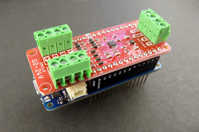
We created the GO-24V MKR shield with 24V tolerant inputs and outputs exactly for this purpose. Just connect it to any board with the Arduino-MKR form factor and go!
Description
The Omzlo GO-24V MKR shield is designed to fit on top of Arduino MKR compatible boards, such as the Arduino MKR Zero. But it really shines as part of an IoT project on top of a Omzlo CANZERO node.
It features:
- 4 digital inputs (0-24V).
- 4 digital open-drain outputs (0-24V), sinking up to 2A.
- 2 analog inputs (0-24V).
The shield also breaks out the GND and VIN pins of the MKR board.
Details
The following table provides details of the shield input/output capabilities:
| Shield connector | Arduino MKR Pin | Characteristics |
|---|---|---|
| Sink 1 (Output) | D0 | 0-24V (max 60V, 3.1A) |
| Sink 2 (Output) | D1 | 0-24V (max 60V, 3.1A) |
| Sink 3 (Output) | D2 | 0-24V (max 60V, 3.1A) |
| Sink 4 (Output) | D3 | 0-24V (max 60V, 3.1A) |
| Input 1 | D4 | 0-24V |
| Input 2 | D5 | 0-24V |
| Input 3 | D6 | 0-24V |
| Input 4 | D7 | 0-24V |
| Analog in 1 | A0 | 0-24V mapped to 0-3.2V |
| Analog in 2 | A1 | 0-24V mapped to 0-3.2V |
| GND | GND | Connected to the GND reference on the MKR board. |
| VIN | VIN | Connected to VIN on the MKR board. |
On an Arduino MKR Zero, VIN will typically be 5V, whereas it can be anywhere between 6V and 28V on a CANZERO.
Note that this shield does not feature isolated inputs/outputs (e.g. using optocouplers) or galvanic isolation.
The digital inputs have the same shifting characteristic as the GPIO of the MCUs they are connected to. For a SAMD21 board like the Arduino MKR Zero or the Omzlo CANZERO, this means that any input below 1V will be considered LOW (0), and any input above 1.8V will be considered as HIGH (1).
The digital outputs are sinking outputs, which means that they are used to switch loads on the low side, as shown in the picture below.
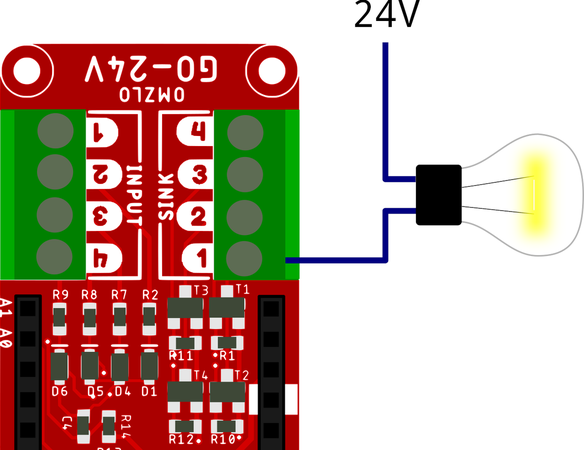
The sinking outputs are controlled by MOSFETs, which have a comfortable maximum 3.1A current rating. In practice, it's best to keep safely away from those limits. We tested currents up to 1.5A without any issue, low-side switching power LEDs. Lower currents should also be considered when switching these MOSFETs very rapidly (e.g. through fast PWM). In doubt, please consult the safe operating area of the MOSFET in the datasheet.
Instead of switching a load, if you want to use the digital output to drive a signal between 0 and 24V (or lower), you will need to add a pull-up resistor between the sinking output and the high voltage level (e.g. 24V), as shown in the example below.
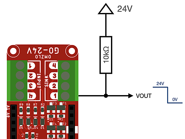
In that case, the logic is inverted: setting the sinking output to "high" sets VOUT to 0V, whereas setting the sinking output to "low" sets VOUT to high (e.g. 24V).
Analog inputs are managed by feeding input voltage in a voltage divider and a buffering op-amp, resulting in a scaled voltage range where 24V corresponds to 3.2V on the analog input of the Arduino-compatible board (and 24.75V corresponds to 3.3V). In terms of accuracy, the voltage divider uses 1% resistors, but the greatest source of inaccuracy can come from the ADC of the MCU itself. It is possible to apply calibration to each board to substantially increase accuracy.
Arduino code
Reading the digital input is as simple as reading any ordinary digital input:
    #define IN1 4
    ...
    pinMode(IN1, INPUT);
    ...
    input = digitalRead(IN1);
Using the sinking output is similarly simple:
    #define SINK1 0
    ...
    pinMode(SINK1, OUTPUT);
    ...
    digitalWrite(SINK1, HIGH);
As noted above, if you are using the sinking output to drive a signal with a pull-up resistor, the logic is inverted:
digitalWrite(SINK1, HIGH)will drive the output to GND.digitalWrite(SINK1, LOW)will drive the output to HIGH (e.g. 24V).
Using the analog input is a bit more complex since voltages need to be scaled to match the input range. For 12-bit analog inputs, the values returned by analogRead() will range from 0 to 4095, where 4095 corresponds to 24.75V using the default internal analog reference and assuming everything is perfectly calibrated (An analog input of 3971 should correspond to 24V).
void setup() {
    analogReadResolution(12);
}

void loop() {
    int a;
    float voltage;
    ...
    a = analogRead(A1);
    voltage = (24.75*((float)a))/4095.0;
    ...
}
Notes:
- By default Arduino is configured to perform 8-bit analog readings. The function analogReadResolution() can be used to change this to 12 bits on supported boards featuring the SAMD21G18 MCU.
- You should expect a few percents of inaccuracy in the reading due to the 1% tolerance of the resistors and because of the ADC itself. Calibration can be used to fix this issue.
Full example
The following Arduino sketch shows a simple program that scans the 4 digital inputs continuously and prints a message each time there is a change.
#define IN1 4
#define IN2 5
#define IN3 6
#define IN4 7

void setup() {
  pinMode(IN1, INPUT);
  pinMode(IN2, INPUT);
  pinMode(IN3, INPUT);
  pinMode(IN4, INPUT);

  Serial.begin(38400);

  while (!Serial);

  Serial.println("Started input pin sensing.");
}

int last[4] = { LOW, LOW, LOW, LOW };
unsigned event_counter = 0;

void loop() {
  char text[40];
  int cur[4];

  cur[0] = digitalRead(IN1);
  cur[1] = digitalRead(IN2);
  cur[2] = digitalRead(IN3);
  cur[3] = digitalRead(IN4);

  for (int i=0; i<4; i++) {
    if (cur[i]!=last[i])
    {
      sprintf(text, "%04u: Input %i is now %s", ++event_counter, i+1, (cur[i]==LOW?"LOW":"HIGH"));
      Serial.println(text);
      last[i]=cur[i];
    }
  }
}
What's included
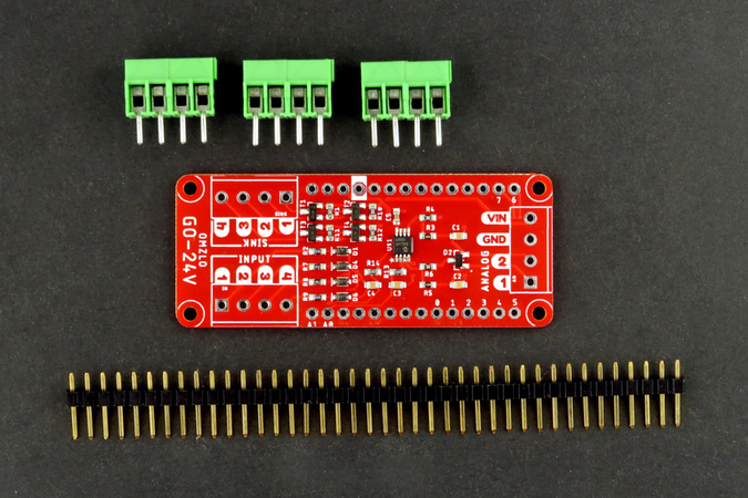
As shown in the picture below, the Omzlo GO-24V MKR shield comes as a shield with the following unsoldered headers:
- One breakable male 2.54mm pin headers (0.1")
- Three 4-pin 3.5mm terminal blocks (colors may vary).
Resources
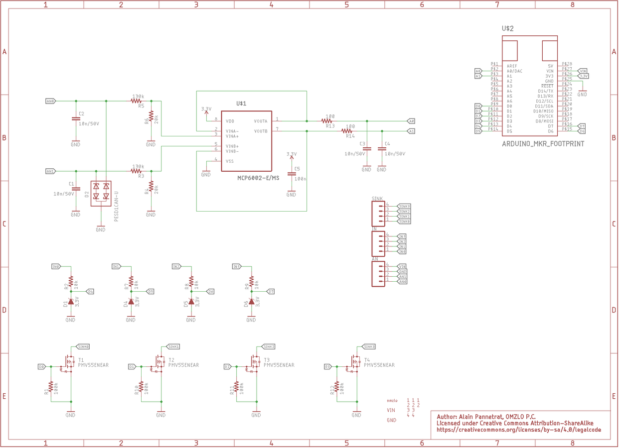
- Board schematics.
- Eagle CAD design files [pending].
The GO-24V Arduino-MKR compatible shield is available on our online shop and on Tindie.
Comments
Hello and good day, I wanted to run an electromagnet with this shield, which needs 24V and around 0.5A. I have programmed the Sink-Output just like your online documentation, but when I check the sink-output with Arduino VCC-pin through my ohmmeter, the voltage is just like the voltage from one arduino pin around 3.3V . Please write to me, what should I actually do to get 24V from this shield. Thank you!
Cheers, Sina Saghi
Sina Saghi, almost 6 years agoHi , just bought 10 of these modules but can't figure out how can I use the output to send a signal to the PLC , without damaging the board. Moreover the mosfet schematic shown in the board schematic is different then that if the mosfet documentation. Any guidance would be really appreciated.
Hamza Shah, over 5 years ago@Hamza Shah: We added some information in the text above that should help solve your problem. See "If you want to use the digital output to drive a signal between 0 and 24V..."
Omzlo, over 5 years agoTheir is no info on what the VIN and GND are connected to.
Hamza Shah, over 5 years ago@Hamza Shah: The description says "The shield also breaks out the GND and VIN pins of the MKR board." We will add this to the table as well.
Omzlo, over 5 years agoAlas!, Just fried my board with giving 24volt on the shield. Now I have to get a new board too. I mean It could have been avoided if this information was provided earlier on the table.
Hamza Shah, over 5 years agoFirst of all your pin out configration is not the same on your documentation page and your shoping page.
hamza shah, over 5 years agoZr5ATVbmCmxo8IG2noIKG1RXAiWBhdd3qdbuRC6RAY1djn6PJJ3qhAdALsG5r
mQjEIRArg0s, over 3 years agoZr5ATVbmCmxo8IG2noIKG1RXAiWBhdd3qdbuRC6RAY1djn6PJJ3qhAdALsG5r
mQjEIRArg0s, over 3 years agoZr5ATVbmCmxo8IG2noIKG1RXAiWBhdd3qdbuRC6RAY1djn6PJJ3qhAdALsG5r
mQjEIRArg0s, over 3 years agoZr5ATVbmCmxo8IG2noIKG1RXAiWBhdd3qdbuRC6RAY1djn6PJJ3qhAdALsG5r
mQjEIRArg0s, over 3 years agoZr5ATVbmCmxo8IG2noIKG1RXAiWBhdd3qdbuRC6RAY1djn6PJJ3qhAdALsG5r
mQjEIRArg0s, over 3 years agoJ9qUWz65VGJ1CBsoUkzDWg0cFnfeRqXlkUQvlpQ79BAviZGdJfgmSDMftXhmj7rPqcxg668nruCZ6EpAb8a6CUfzVJJTP7HZ8LaKGM3ruEzgoqtcXxZtErPHbJiyq4V6f8CB4D8IlF2rebdt9gNdCsK7vPlO
tw1GUTF4QFKmERs, over 3 years agoJ9qUWz65VGJ1CBsoUkzDWg0cFnfeRqXlkUQvlpQ79BAviZGdJfgmSDMftXhmj7rPqcxg668nruCZ6EpAb8a6CUfzVJJTP7HZ8LaKGM3ruEzgoqtcXxZtErPHbJiyq4V6f8CB4D8IlF2rebdt9gNdCsK7vPlO
tw1GUTF4QFKmERs, over 3 years agoJ9qUWz65VGJ1CBsoUkzDWg0cFnfeRqXlkUQvlpQ79BAviZGdJfgmSDMftXhmj7rPqcxg668nruCZ6EpAb8a6CUfzVJJTP7HZ8LaKGM3ruEzgoqtcXxZtErPHbJiyq4V6f8CB4D8IlF2rebdt9gNdCsK7vPlO
tw1GUTF4QFKmERs, over 3 years agoJ9qUWz65VGJ1CBsoUkzDWg0cFnfeRqXlkUQvlpQ79BAviZGdJfgmSDMftXhmj7rPqcxg668nruCZ6EpAb8a6CUfzVJJTP7HZ8LaKGM3ruEzgoqtcXxZtErPHbJiyq4V6f8CB4D8IlF2rebdt9gNdCsK7vPlO
tw1GUTF4QFKmERs, over 3 years agoJ9qUWz65VGJ1CBsoUkzDWg0cFnfeRqXlkUQvlpQ79BAviZGdJfgmSDMftXhmj7rPqcxg668nruCZ6EpAb8a6CUfzVJJTP7HZ8LaKGM3ruEzgoqtcXxZtErPHbJiyq4V6f8CB4D8IlF2rebdt9gNdCsK7vPlO
tw1GUTF4QFKmERs, over 3 years ago14 comments triggered our SPAM filter and will be reviewed before publication.
Leave a comment