
In a previous blog post, we described "SKWARE" our revised Arduino-compatible IoT modules. These nodes are designed to be connected together in a daisy-chain fashion with a single cable that brings both DC power and CAN-bus networking. The voltage transported in the cables is not 5V (or 3.3V) but rather 12V or 24V to work more comfortably over long distances, potentially reaching 300 meters (1000 feet). You can think of it as a poor man's PoE.
This network of connected nodes is designed to be monitored and controlled by a "master node", which injects the necessary 12V/24V DC, provides node management services and a web interface for network administration. While the IoT nodes are based on an Arduino-style microcontroller, the "master node" requires a bit more power. In this context, the ubiquitous Raspberry Pi with its GPIO header seems like an ideal candidate for that role and we decided to see if we could build a "master node" by augmenting a Raspberry Pi with an appropriate add-on board. These add-on boards are called "HATs" (for "Hardware Attached on Top") and we called our first prototype the "Pi Master HAT".
The drawing below illustrates the general structure of our network. A Raspberry Pi equipped with our "Pi Master HAT" controls a network of 2 (or more) daisy-chained nodes, like the SKWARE.
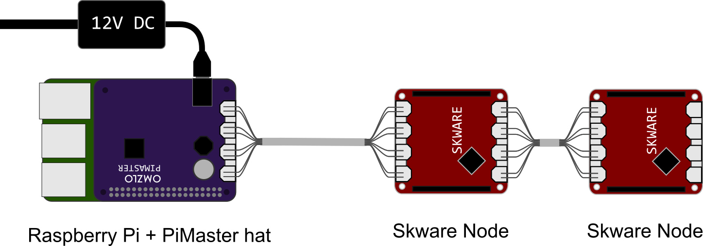
In the drawing above, the "Pi Master HAT" is used to inject the 12V (or 24V) required in the network. As such, it needs to be connected to a 12V (or 24V) power supply. In order to avoid having two distinct power supplies --one for the Raspberry Pi and one for the network--, it seems logical to use a single power supply for both by putting a step-down voltage converter on the "Pi Master HAT" providing the 5V needed for the Raspberry Pi.
Going further, we defined the key requirements of our Pi Master HAT as follows:
- Provide power to the raspberry PI with 5V, up to at least 1A.
- Host a microcontroller as an interface between our CAN-bus network and the Raspberry Pi.
- Use SPI or I2C for efficient communication between the HAT and the Raspberry Pi.
- Provide the ability to monitor and switch on/off the DC power injected into the network.
- Provide some protection in case of short circuits in the network.
- Provide a serial line between the microcontroller and the Raspberry Pi for debugging purposes.
Design overview
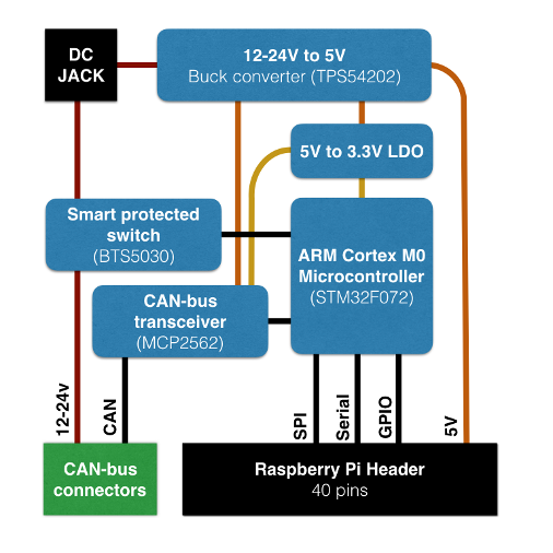
A very high-level schematic diagram of our "Pi Master HAT" is shown below.
The step-down converter
We started with the step-down voltage converter which takes the 12V to 24V input voltage down to 5V to power the Raspberry Pi. We didn't want to use a linear voltage regulator here since it would induce a big waste of power dropping 12V or 24V to 5V for the Raspberry Pi. After a few hesitations, we settled for the TPS54202, which is advertised by TI as a 4.5-V to 28-V Input, 2-A Output, EMI Friendly Synchronous Step Down Converter. It seemed like a good compromise between cost, board space, and performance. Thanks to our HAT, the Raspberry Pi can now be powered by a simple DC jack!
This circuit could be used in other Raspberry Pi project, so we reproduce it below.
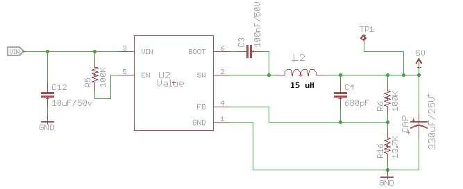
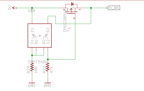
Initial rough measurements showed 80mv of ripple/noise on the 5V output, but a more careful measurement would probably conclude with better results. This 5V output then goes through a so-called "ideal diode", which protects the Raspberry Pi in case it is already powered by USB. This should not normally happen, but you never know. It's a really neat little circuit as explained here.
The microcontroller
We next selected a microcontroller that was capable of working with CAN-bus, provided SPI/I2C, serial lines and the necessary extra GPIO pins we needed. We have gained some good experience with the STM32F042 that is used in our IoT nodes, both the original Omzlo One and the SKWARE, so we looked for something in the same family. We picked the STM32F072, a rather cheap ARM cortex M0, which had all the necessary peripherals and can be clocked at 48Mhz without any external oscillator. This chip also has USB but we finally decided not to use that feature.
A 3.3V LDO
Since both the STM32F072 and the Raspberry Pi GPIO operate at 3.3V, we added a simple 3.3V/300mA LDO on our board (a MIC5504-3.3), which conveniently only needs two 1 uF caps to operate smoothly.
A smart power switch
To allow the microcontroller to switch on or off the 12-24V DC power in the network, we wanted to use a "high side" switch so that nodes are always connected to ground even when power was disconnected. A simple P-channel MOSFET with a few extra components would work, but we wanted something a bit smarter, with the capability to shut off in case of over-current or short circuit. It's possible to add those features to a P-channel based switch but it starts to add more complexity and cost. Instead, as we did in the past, we settled for one of those neat little high side power switches by Infineon: the BTS5030. These devices are actually based on an N-channel MOSFET, but use an internal charge pump to reach the right gate threshold voltage. They are packed with plenty of nice protection features, including short circuit detection.
The CAN-bus transceiver
We selected the Microchip MCP2562 as our CAN-bus transceiver. As most CAN-bus transceivers, this chip requires a 5V power supply, but it accepts 3.3V level logic i/o which makes it very easy to integrate with our microcontroller.
Headers
Finally, we added a few pin headers, notably 4 pins to program the STM32 through SWD and 4 other for access to the serial line of the microcontroller just in case.
Assembling a first prototype of the Pi Master HAT
We created the schematics and board, placed an order on oshpark, and waited a few weeks for the purple boards to arrive. We hand-soldered the first board and got the result shown in the picture below.
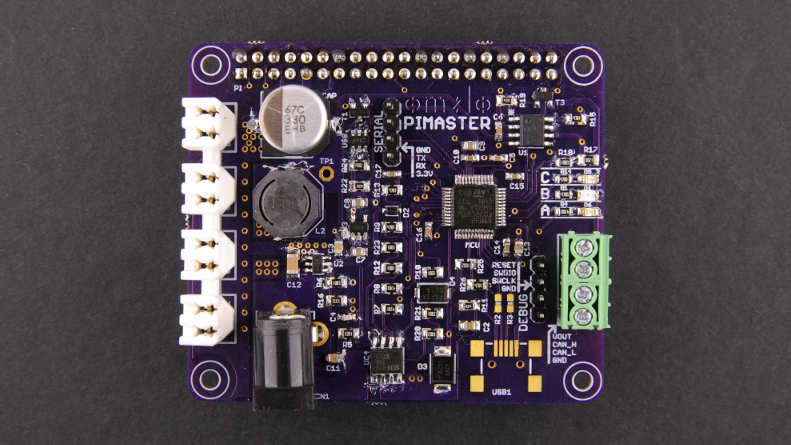
We didn't bother with soldering the USB connectors. In the end, it does not provide any added value and would create a lot of extra work for firmware support.
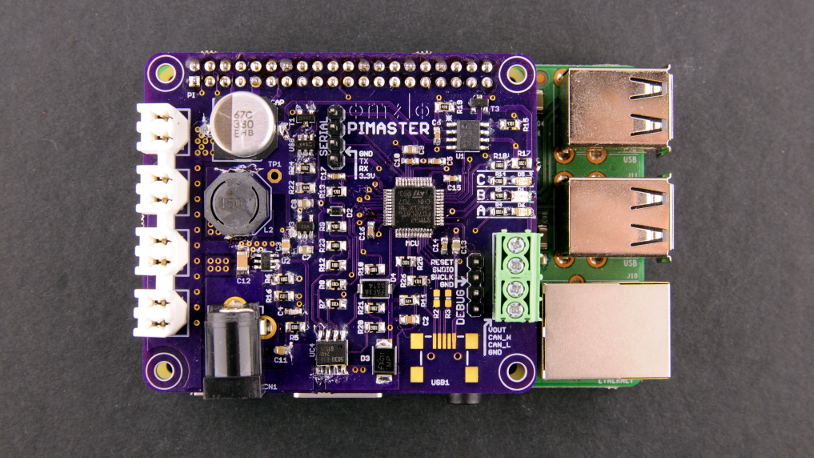
The picture below shows our prototype on top of a Raspberry Pi.
Using the prototype
The STM32 is connected to the Raspberry Pi as follows:
- The STM32's SPI 1 is connected to the Pi's GPIO 8, 9, 10 and 11 (SPI 0).
- The STM32's USART 4 is connected to the Pi's GPIO 15 and 14 (UART 0).
- One of the STM32's IO Pin is connected Pi's GPIO 22, to signal packet reception.
- One of the STM32's IO Pin is connected Pi's GPIO 25, to signal packet sending in progress.
The Pi and the STM32 mainly communicate over SPI, with the Pi acting as a master sending requests, and the STM32 acting as a slave responding to those requests. The SPI protocol we developed notably offers the following functions:
- Send a CAN packet.
- Receive a CAN packet.
- Read message status registers, voltage levels, etc.
- Enable/disable power on the network through the smart power switch.
- Enable/disable the 120 ohms CAN bus termination resistors.
In our firmware, the STM32 sets the pins connected to the Pi's GPIO 22 and 25 to a high state in output mode. Conversely, those GPIO pins are configured as inputs on the Pi. When a CAN packet is available from the network, GPIO 22 goes to low and remains so until all pending received packets are read through SPI. Similarly, when the Pi uses an SPI command to send a packet to the network, GPIO 25 goes low until the packet has effectively been sent and the microcontroller is available to send a new packet. The software on the Pi uses interrupts tied to GPIO 22 and 25 in order to know when packets can be received or sent, thereby avoiding a busy loop and unnecessary polling of the SPI interface on the Pi.
Finally, the serial line between the STM32 and the Pi allows a bit of debugging. On a Raspberry Pi 2B, simply use the screen utility to connect to the "Pi Master HAT":
screen /dev/ttyAMA0 115200
Our current firmware then provides access to a little minimalistic debugging terminal.
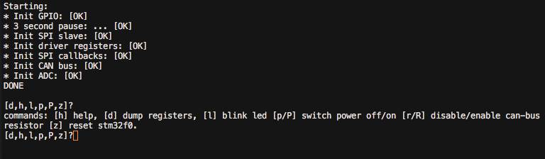
Note: Raspberry Pi 3 users beware, connecting to serial is more complicated than on the Pi B2
Programming
We wanted to test our new HAT in the field, so we put it outside in a protected enclosure and connected it to a few nodes. We quickly faced an unforeseen challenge: how can we remotely update the HAT's firmware without physically accessing it each time we want to make an update? Well, it turns out that you can program/debug the HAT from the Rasberry Pi itself! As shown below, you can simply plug one of those cheap Chinese STM32 SWD programmers from eBay in a USB port of the Raspberry Pi and plug the SWD headers in the HAT, leaving everything in place in the enclosure. You just need to compile and install the texane/stlink utility on the Pi and you are up and running.
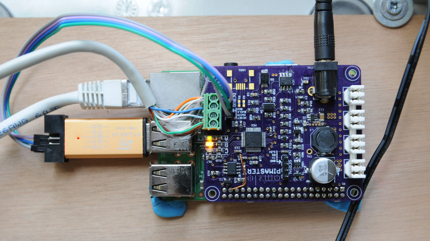
So the HAT powers the Pi, and the Pi powers the USB programmer, which itself is used for debugging the HAT. It's got a nice recursive feel to it, no?
What next?
Our firmware works on a basic level and we successfully used it to test CAN-bus communications over 300 meters (1000 feet). We have a running test network that has been up for several days without any issue. Of course, it will need more testing, fine tuning, and error handling. The SPI communications currently work reliably up to 250Kbps but we would like to see if code improvements could lead to 500Kbps or more.
We will likely move to an even cheaper brother of the STM32F072 since we don't need USB.
One problem we encountered was performing a hard reset of the STM32 microcontroller: while we have exposed a reset header pin, it seems that those Chinese STM32 SWD programmers are not capable of using it (or perhaps the texane/stlink utility does not implement that function). Luckily, we were able to add a small wire between a via on the microcontroller's reset line and one of the GPIO. We can then reset the microcontroller by setting that pin to 0 and then back to 1. This can be done from the command line with the WiringPi gpio utility. You can actually see the wire we added on the previous picture featuring the debugger.
Our next design will integrate this feature and a few other minor improvements. In a future article, we plan to go through a detailed view of the schematics and design files, as we get closer to the final version of our "Pi Master HAT".
As shown in many pictures in this article and previous ones, we have been using punch-down blocks as a way to connect cables in our network taking advantage of the fact that UTP Ethernet cables are cheap. In practice in the field, these connectors have been more trouble than we thought. It's difficult to be certain that they are correctly connected and they are impractical when you want to experiment, plugging and unplugging nodes frequently. We will likely move back to simple screw-mount terminals in future iterations of our project unless a better idea comes our way.
To keep being updated about this project, follow us on twitter or on our facebook page.
NOTE: Check out the Pi Master HAT for an updated description of this project.
Comments
No comment yet
Leave a comment