
A few weeks ago we launched a Kickstarter to finance the first production run of the Omzlo One, an Arduino compatible board that you can daisy-chain with other similar boards to form an IoT network you can program and control from your PC or a simple Raspberry Pi. The boards are connected together with a single cable that brings both power and networking, using CAN-bus, as detailed on the project page.
Unfortunately, the project didn't reach its funding goal.
There are probably many reasons for this failure. This was our first Kickstarter and there are many things that we could have done better, including marketing, pricing, and technology demonstration. But on the positive side, we got also plenty of positive feedback, constructive criticism and new ideas from Kickstarter backers and even from hackaday readers. This has encouraged us to continue to work on this idea with a goal of coming back to crowdfunding in a few months with a better product. We also want to document this process more openly, hopefully to continue to get feedback and improve this project.
This article is the first step of this process.
Re-designing the Omzlo One
As we go back to square one, we started experimenting re-designs of the Omzlo One board. We came up with two ideas:
- Make it smaller and drop the Arduino form factor, keeping pinout and software compatibility.
- Replace RJ45 connector with something more practical for garden/exterior projects.
Smaller
Making the board smaller means that the PCB is cheaper to produce. More importantly, it makes it easier to fit in enclosures and electrical boxes. As a starting point, we looked at electrical junctions boxes at the local hardware store: the smallest ones are 6cm by 6cm (~2.3 inches) so we settled on a maximum board size of 5cm by 5cm (~2 inches).
By dropping the Arduino form factor for a smaller one, we can also adopt a more sane header spacing, without the infamous gap that makes Arduino breadboard unfriendly.
The picture below shows the resulting new red PCB next to its older green sibling.
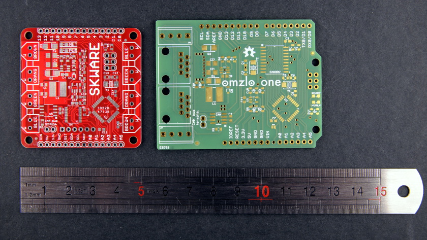
It is 1.95"x1.95" (5cm x 5cm). Since it's square hardware, we decided to call it "SKWARE" :-)
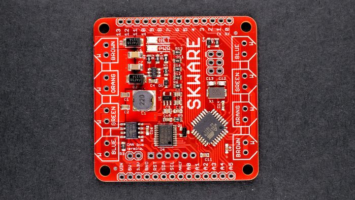
Here it is right after it came out of the reflow oven.
We also have a similar sized PCB prototype were the Atmega328pb has been replaced with an Arm Cortex M0+, a SAMD21G18A like on the Arduino Zero, but we didn't take the idea much further since it would require a lot of changes on the software side without clear benefits.
Punch down blocks
The Omzlo One uses RJ45 sockets to connect. This design choice was largely guided by cost considerations: while we only need 4 wires to connect our CAN-bus based network, the use of Ethernet cables with 8 wires allows us to take advantage of the fact that these cables can be found for very cheap. This is nice for demos and indoor projects: you can quickly plug and unplug boards together. Unfortunately, things get more complicated for outdoor projects hosted in enclosures: you need either to drill holes that are big enough to pass through an RJ45 plug, or you use a plain UTP cable that you crimp to the RJ45 connector once it has passed through a hole drilled in the enclosure.
None of these approaches are fully satisfactory.
But then we found an interesting alternative with punch down blocks that you can find in patch boards. We can keep using Ethernet cables but the boards will be easier to put in enclosures outside.
The picture below shows the new "SKWARE" board with the punch down blocks and debug headers, connected for initial testing.
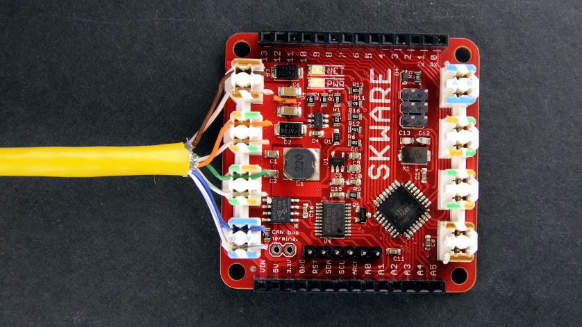
This first design revision has a few minor mistakes. The punch-down blocks are mounted backward and the bottom and top headers are not correctly spaced apart :-) We will fix that soon.
Next, we plan to replace the "Omzlo USB controller" with a Raspberry Pi HAT, giving us more bandwidth through a direct SPI connection. This other experiment will be the topic of another post.
Using 4 twisted pairs
Added on July 10, 2017, following comments
Though you only need a minimum of 4 wires (2 twisted pairs) to connect the Omzlo Skware (or the Omzlo One), we use all 8 wires (4 twisted pairs) provided in an Ethernet UTP cable for our connections.
The 8 wires are used as follows:
- 2 wires for CAN-bus (one twisted pair)
- 3 wires for DC power input (one and a half twisted pairs)
- 3 wires for ground (one and a half twisted pairs)
The reason for this arrangement has to do with reducing power loss in cables over long distances. Consider a case where you create a network with an Omzlo Skware connected over a 100-meter 24-AWG ethernet cable powered with 24V DC with an application that requires 1A of current (100 meter is approx. 328 feet).
According to this calculator:
- When using a single wire, the voltage drop over 100 meters is 16.8V, leaving you with just 7.2V!
- When using 3 wires, the voltage drop over 100 meters is 5.61V, leaving you with 18.39V.
Clearly the second case leaves you in a more comfortable situation. Of course, the above example of an application using 1A is a bit extreme: the Omzlo Skare itself uses less than 20mA at 24V, leading to negligible cable losses. But it illustrates the point: the more copper you have, the better!
Tell us what you think
So do you like "SKWARE", the new smaller replacement of the Omzlo One? Comments and feedback are welcome!
Note: since this blog entry was posted, many things changed and we launched a new successful Kickstarter with the NoCAN platform
Comments
Looks great, take my money.
Elba Stevenson, about 9 years agoI liked the RJ45 sockets. I can see arguments both ways so I wonder if there is a way you could choose like a separate breakout board for the cables. Or maybe two versions to cover both needs.
Justin Butler, about 9 years agoWow, this is really slick. Are the two extra pairs on the ethernet cable used for anything? Not sure why there's punchdown sites for them if they are not needed.
Joe Walsh, about 9 years ago@JoeWalsh I edited my article to answer your question -- See "using 4 twisted pairs".
Alain, about 9 years agoThanks for sharing your thoughts and feedback ! Possibly quite a noob question as I am no master of electronics wizardy : considering that - the Ethernet cables are foiled/shielded; - the SKWARE are meant to be daisy-chained; wouldn't it make sense to have some kind of connection of the foil/shield between the different cables sections of the daisy chain ?
Ping, almost 9 years ago@ping: Not all ethernet cables are shielded: see for example "UTP" cables.
If you are doing high-speed Ethernet, it's true that might be better to take shielded cables, but for an application like this, UTP cables are fine. As such, there is no need to worry about the shield continuity here.
Alain, almost 9 years agoSKWARE doesn't seem to have any indicators that a certain message was received..
I'm looking for a simple CanBus node that I can send data to to just verify that the bus/master-controller is working.
I prefer something completely off the shelf that doesn't require any programming. Just need what bytes are needed to turn on some kind of indicator.. led/relay/buzzer/etc.
I've only been able to find either boards that require programming.. or can sensors that are hundreds of dollars. Any suggestions?
ben, about 7 years agoLeave a comment