
Most modern microcontroller boards cannot be connected to logic levels greater than 3.3V (sometimes 5V). For this reason, we created the GO-24V MKR, a shield which enables our CANZERO IoT node or an Arduino MKR to interface with systems up to 24V. This shield notably has two analog inputs that translate the voltage range 0-24V to 0-3.2V, which is suitable for the ADC of the modern microcontrollers.
As we wrote Arduino sketches to test this shield on our own CANZERO IoT nodes as well as on the Arduino MKR Zero, we noticed that measurements were all offset by about +35mV. In other words, all ADC readings on these boards were overestimating their input by about 35mV. These boards have one thing in common: they use the Microchip/Atmel SAMD21 Arm Cortex M0+ 32-bit microcontroller. Further tests across multiple analog pins and multiple SAMD21 boards showed offset errors ranging between 25mV and 57mV.
What was happening here?
Is the Arduino ADC wrong?
We decided to remove the shield and test the ADC of these SAMD21 Arduino-compatible boards directly to examine whether the GO-24V might be introducing some unexplained error. So we connected a voltage source to Analog pin A0 on an Arduino MKR Zero board combined with a voltage meter. We created the following simple Arduino sketch to report ADC measurements on pin A0 every second, on the serial USB output:
#define Debug Serial

void setup() {
  analogReadResolution(12);
  pinMode(A0, INPUT);
  Debug.begin(9600);
  while (!Debug);
}

void loop() {
  int a = analogRead(A0);
  float v = 3.3*((float)a)/4095;

  Debug.print(a);
  Debug.print(" ");
  Debug.print(v,3);
  Debug.println();

  delay(1000);
}
Next, we went through different target voltages: 0V, 0.5V, 1.0V, 1.5V, 2.0V, 2.5V, 3.0V and 3.3V. The table below shows the results of our measurements:
| Target Voltage | Meter Reading | ADC reading | Error in mV |
|---|---|---|---|
| 0.0 V | 0,005 V | 0,039 V | 34 mV |
| 0.5 V | 0,502 V | 0,533 V | 31 mV |
| 1.0 V | 1,004 V | 1,035 V | 31 mV |
| 1.5 V | 1,503 V | 1,538 V | 35 mV |
| 2.0 V | 1,999 V | 2,033 V | 34 mV |
| 2.5 V | 2,498 V | 2,535 V | 37 mV |
| 3.0 V | 3,001 V | 3,037 V | 36 mV |
| 3.3 V | 3,300 V | 3,300 V | 0 mV |
The column named ADC reading corresponds to an average of several values v provided by the Arduino sketch.
The test confirms the existence of an offset error of about 35mV in the ADC readings. The error is 0 for 3.3V only because the ADC saturates and cannot actually measure a voltage above 3.3V, which presumably here would otherwise register as 3.335V.
After the Arduino MKR Zero, we repeated the sketch with our CANZERO IoT node and also a Sparkfun SAMD21 breakout board. We also tried a different meter from different bands.
The results were still the same.
We also note that the offset error appears when the analog input is connected directly to GND, which rules out metering errors.
For simplicity, the above sketch assumes that VCC is exactly 3.3V. In reality, depending on the LDO on the board, the value of VCC might be slightly different. For even more accurate results, you can measure the value of VCC on your board and replace the 3.3 value in the line float v = 3.3*((float)a)/4095; with the actual measured value of VCC (e.g. 3.29V). You will see that this does not change the results in any significant way.
Update Sept. 3, 2019: As correctly noted by Alexander Entinger on the Arduino Github, we should have used float v = 3.3*((float)a)/4096; in our sketch (and even add 0.5f to a). Our division by 4095 (instead of 4096) allows values to nicely scale to 3.3V but introduces a small distortion of maximum 0.9mV in the results. This is no impact on our findings but is useful to consider when writing correct ADC code.
Is the SAMD21 ADC so bad?
A simple solution to fix this voltage offset is to subtract 35mV (or whatever the offset is) in the readings. The measurements become quite accurate then, at the expense of a small loss of range. Arduino provides a calibration tool for the SAMD21 that can help with this purpose. Yet it was still surprising to see such a problem on a microcontroller.
The only alternative explanation would be that there is a bug in the implementation of the Arduino analogRead() giving readings with an offset. To test this hypothesis we rewrote our own crude "baremetal" version of analogRead() limiting it to the pin A0. The function called adcRead() is shown here in the modified sketch below:
#define Debug Serial

void setup() {
  analogReadResolution(12);
  pinMode(A0, INPUT);
  Debug.begin(9600);
  while (!Debug);
}

uint32_t adcRead(void)
{
  REG_ADC_CTRLA = 2;
  REG_ADC_INPUTCTRL = 0x0F001800;
  REG_ADC_SWTRIG = 2;
  while (!(REG_ADC_INTFLAG & 1));
  return REG_ADC_RESULT;
}

void loop() {
  int a = adcRead();
  float v = 3.3*((float)a)/4095;

  Debug.print(a);
  Debug.print(" ");
  Debug.print(v,3);
  Debug.println();

  delay(1000);
}
Again, we went through different target voltages: 0V, 0.5V, 1.0V, 1.5V, 2.0V, 2.5V, 3.0V and 3.3V. The table below shows the results of our measurements:
| Target Voltage | Meter Reading | ADC reading | Error in mV |
|---|---|---|---|
| 0.0 V | 0.006 V | 0.010 V | 4 mV |
| 0.5 V | 0.505 V | 0.506 V | 1 mV |
| 1.0 V | 1.004 V | 1.005 V | 1 mV |
| 1.5 V | 1.502 V | 1.506 V | 4 mV |
| 2.0 V | 1.999 V | 2.003 V | 4 mV |
| 2.5 V | 2.499 V | 2.504 V | 5 mV |
| 3.0 V | 3.001 V | 3.006 V | 5 mV |
| 3.3 V | 3.300 V | 3.300 V | 0 mV |
Suprise! The rewritten function shows a much more accurate reading of analog values, with an error in the 1 to 5mV range. In this case, some of the measured error might even be attributable to the cables used to connect the meter or the meter itself or a slight imprecision in VCC (assumed for simplicity to be exactly 3.3V). Indeed, repeating the experiment with the actual measured value of VCC leads to errors that are even lower.
The conclusion is surprising but clear: there is a bug in the analogRead() function in the Arduino SAMD21 core.
So what's the problem doc?
A quick look a the Arduino SAMD21 code reveals something suspicious in the following excerpt from the file wiring_analog.cc:
  ...
  ADC->CTRLA.bit.ENABLE = 0x01;             // Enable ADC

  // Start conversion
  syncADC();
  ADC->SWTRIG.bit.START = 1;

  // Clear the Data Ready flag
  ADC->INTFLAG.reg = ADC_INTFLAG_RESRDY;

  // Start conversion again, since The first conversion after the reference is changed must not be used.
  syncADC();
  ADC->SWTRIG.bit.START = 1;

  // Store the value
  while (ADC->INTFLAG.bit.RESRDY == 0);   // Waiting for conversion to complete
  ...
The Arduino code disables the ADC between each measurement (not shown above). It re-enables the ADC at the start of the analogRead() function.
As such, the first measurement probably needs to be discarded as noted as a comment in the code. However, in reality, the first measurement is not completed at all, which normally would require the busy-wait while (ADC->INTFLAG.bit.RESRDY == 0).
Instead, the relevant ADC->INTFLAG bit is reset.
So there is in fact just one measurement here, which is the likely cause of the error. To confirm this, we reproduced that particular feature of the Arduino code in our "baremetal" version above and the offset error appeared again.
For details about the SAMD21 ADC, see section 33 of the datasheet.
Update: how to quickly test this bug on your board
Added Aug. 29, 2019
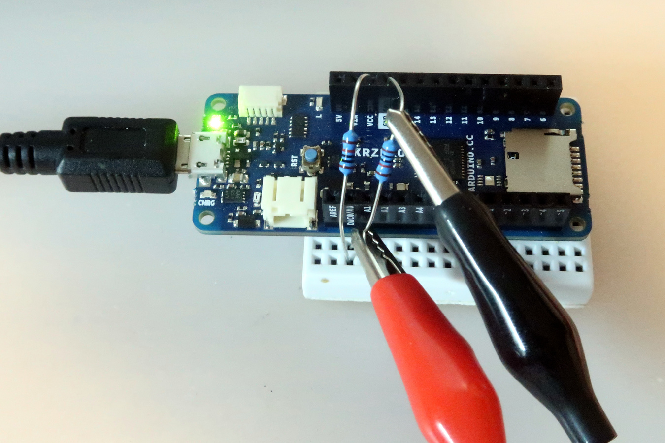
If you don't have a variable voltage source as we used in our own testing, you can use just a couple of 10K resistors (1%) and a good meter to check the bug for yourself:
- connect the first 10K resistor between the GND pin and A0.
- connect the second 10K resistor between the VCC pin and A0.
Next measure the voltage across the first resistor, between GND and A0. With VCC=3.3V, if the resistors are perfectly the same, you should see VCC/2 or 1.650V on the meter. In reality, because the resistors typically have a tolerance of 1%, you might see a value slightly above or below (e.g. 1.641V). Take note of that value.
As an example, this setup is pictured below using an Arduino MKR ZERO:
Now, run the very first Arduino sketch we showed above, with the original analogRead() function and compare the measured results with what you saw on the meter. You should see an offset error of 25mV to 50mV.
Next, you can remove the resistor between VCC and A0. This leaves A0 connected to GND only. Running the first Arduino sketch again should show a measurement of 25mV to 50mV, instead of a couple of mV of noise as one would expect.
You can also try our second sketch, with our own adcRead() function and notice results that are much closer to what the meter shows.
Conclusion
The SAMD21 microcontroller ADC works fine. However, there is a bug in the code of the Arduino analogRead() on the SAMD21 platform.
To be honest, the documentation of the SAMD21 is not super clear and has caused us a lot of head-scratching in the past. What seems stunning is that this bug has existed for at least 4 years, affecting boards from Arduino, Sparkfun, Adafruit and many more and nobody has noticed. How many thousands of Arduino projects have been providing wrong readings?
Did you ever wonder about your Arduino analog reading accuracy? Share your story with us on Twitter or on our Facebook page.
Update Sept. 4, 2019: The bug has been corrected by the Arduino team in a recent PR.
Comments
Pretty amazing indeed that it went unnoticed. Then again, since Arduino mostly targets people that don't want to look under the hood... are we really surprised that no one did? :D
Sébastien, almost 7 years agoI can confirm this is the case. I fixed wiring_analog.c instead by adding an extra while before the 2nd read is initiated
Jim, almost 7 years agoNice catch, please report the bug so they fix it!
Michael, almost 7 years agoMostly used the analog for ratio in crude proportions.. Thanks very much for the alert! Don
Don Latham, almost 7 years agoHello, I have the last official samd21 core 1.8.3 but I still have these bug.
How can I fix it ? Thank you
Nik, almost 7 years agoSame issue here. I have an Adafruit Metro0. I get less then half counts (with the second script) in the offset when the analog is connected to GND. Anyone knows how to do implement the bug fix corrected by the arduino team? I also update the samd21 and other libraries in Arduino IDE. Can anyone point us there?
GL, almost 7 years agoHello, very interesting description and indeed it seem to improve my situation with an Adafruit Feather M0. I have to read A0, A1, A2 and A3 in a row. How do I adjust the adcRead to cover these inputs as well. i don't fully understand the datasheet?
Christoph, almost 6 years ago[url=http://slkjfdf.net/]Eyniyosn[/url] Ibidjame owp.adwl.omzlo.com.rfw.mq http://slkjfdf.net/
ehajobvora, over 3 years ago2 comments triggered our SPAM filter and will be reviewed before publication.
Leave a comment