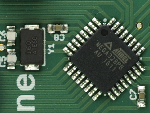
To build "Omzlo One", our IoT Arduino-compatible board, we used the Atmega328PB. Compared to the Atmega328P that powers the classic Arduino UNO R3, the Atmega328PB notably offers an extra I2C line that does not reside on any of the pins that the classic Arduino UNO uses, enabling us to connect a network driver IC without using up any "official" Arduino pins. It also offers an extra SPI line, and an extra UART!
But there is another important difference between the Atmega328P and the Atmega328PB: the latter does not have a "full swing crystal oscillator driver". This change created a lot of debate online. Many suggested that it was not possible to use a crystal and a couple of capacitors to clock the chip as you do with the Atmega328P and that you needed to add your own active driver (e.g. using 74HC04 hex inverters).
We had no idea about this issue until we read about it online. Certainly our Omzlo One boards seemed to run at 16Mhz, using just a crystal and two 20pF caps. Could it be that we had not noticed that our chips were in fact running at 1Mhz (the fallback frequency if the oscillator fails)? Possibly embarrassing...
As a test we did quick program shown below that does PWM on pin D5, toggling the pin value every CPU cycle: on a 16Mhz system, this should output a 8Mhz square wave.
#include <avr/io.h>

int main(void)
{
    // Do PWM on pin D5, reaching 8Mhz

    DDRD = (1<<5);
    TCCR0A = _BV(COM0A1) | _BV(COM0B1) | _BV(WGM01) | _BV(WGM00);
    TCCR0B = _BV(WGM02) | _BV(CS00);
    OCR0A = 1;
    OCR0B = 0;
    while (1);
}
A quick look at the oscilloscope gave us some reassurance. It is a 8Mhz square wave indeed.

We took the opportunity to quickly probe the XTAL1 pin of the Atmega328PB, which gave us the output below.

The signal is not super strong, but it's enough to clock that Atmel328PB. It seems that problems appear with 20Mhz crystals.
For information, we used the following parts:
- ABRACON ABM3-16.000MHZ-B2-T, Crystals +/-20ppm 16MHZ, 18pF
- Kemet C0805C200J5GACTU, 20pF, C0G, 50v, 5%
Placing the crystal close to the MCU is always a good idea and probably also helps here.


Comments
PWM on PD5 is OC0B channel, why you set COM0A1 - is used to channel A COM0An: Compare Output Mode for Channel A [n = 1:0] // try this line: TCCR0A = _BV(COM0B1) | _BV(WGM01) | _BV(WGM00);
Tom, over 7 years agoThanks for the write up on the 328PB working at 16 but not 20 MHz. I recently had a project where I needed to slightly overclock to 20.5 Mhz -- which should have been fine, right? But no. The thing didn't work. This had me stumped for a long time until I was reading up on adding AVRDUDE support for the 328pb and there was a little blurb saying something about the full swing crystal driver... Then I found your page and everything made sense!
Joseph, over 6 years ago[url=http://slkjfdf.net/]Asizul[/url] Ulfnujomg ulx.qece.omzlo.com.ekk.sx http://slkjfdf.net/
edisuofuqocim, over 3 years agoLeave a comment