
Note: This article refers to a prototype. The final product is described here.
I'm showcasing the latest prototype of the Omzlo platform at Maker Faire Rome 2017, next to the Arrow booth and the Arduino booth!
Today, when building IoT network, many of us rely on WiFi or Bluetooth. But such wireless solutions are not adequate for all applications: the signal does not always reach where it's needed, and you may find yourself running into power issues (e.g., changing batteries all the time). You may realize that a "wired" solution is a better approach.
The Omzlo platform offers an easy way for makers to build an Arduino-compatible "wired" IoT network for their home and garden, using just a simple cable that provides CANbus networking and DC power.
Description
An Omlzo network is composed of one or more nodes connected to a node manager, forming a chain. Each node is an Arduino-compatible device called "CANZero," which can be programmed using the familiar Arduino IDE and libraries. The node manager is composed of a Raspberry-Pi connected with a HAT (i.e., a shield) called the "PiMaster," which provides a web interface that enables users to manage their network. The following drawing illustrates the topology of this network.
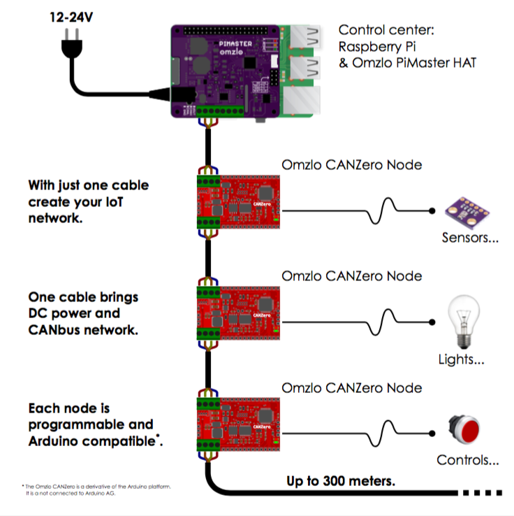
Each "CANZero" node in the network can communicate with any other node in the network, using a simple "publish/subscribe" mechanism. For example, a first CANZero could be programmed to measure and report soil humidity, while the second CANZero would be programmed to activate the watering system depending on the values provided by the first node.
Users can write code and then upload the result to any CANZero node in the network through the web-interface provided by the "PiMaster" controller. As a consequence, there is no need for physical access to the node to program it. In fact, the nodes can be far away from the controller: we have tested the network over distances of 300 meters without any issue.
Technical details
Network
The Omzlo network requires a four-wire cable:
- Two wires for DC power, typically featuring 12V or 24V.
- Two wires for the CANbus differential signal.
The CANZero
The CANZero node is an Arduino-compatible board with similar characteristics to the Arduino Zero, with the addition of unique features necessary for networking. It notably features:
- A SAMD21G18, an ARM Cortex M0 microcontroller at 48Mhz.
- An STM32F042 microcontroller for network management.
- A step-down switching regulator providing 5V and 3.3V.
- A CANbus transceiver.
- 20 GPIOs pins (including I2C, SPI, serial and ADC/DAC)
The diagram below gives a simplified overview of the pinout of the CANZero.

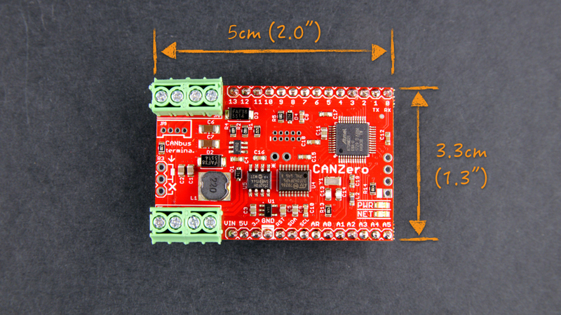
Measuring 3.3cm by 5cm (1.3" by 2"), the CANZero is smaller than the classic Arduino and can fit in an electric junction box if necessary, as shown in the picture below.
The role of the STM32F042 is to free the main microcontroller (the SAMD21G18) from network management tasks. It can also "reset" the main microcontroller in case of an issue or to upload new code to the main microcontroller.
The PiMaster HAT
The "PiMaster" HAT (shield) connects to a RaspberryPi and a 12V to 24V power source. It has three roles:
- Power the Raspberry Pi by stepping down the 12V/24V to 5V.
- Inject power into the CANbus network, with monitoring providing automatic shutdown in case of overcurrent/short circuits.
- Act as a gateway between the CANbus network and the Raspberry Pi (using SPI).
The "PiMaster" features:
- an STM32F042 microcontroller (an ARM Cortex M0 running at 48Mhz).
- A 5V step-down regulator for 2A max.
- A high-side smart switch (e.g., Infineon BTS5030).
- A CANbus transceiver.
Learn more
Stay tuned to learn more about the Omzlo platform. It will be released as open-source/open-hardware. Follow us on twitter or on our facebook page.
Comments
No comment yet
Leave a comment