
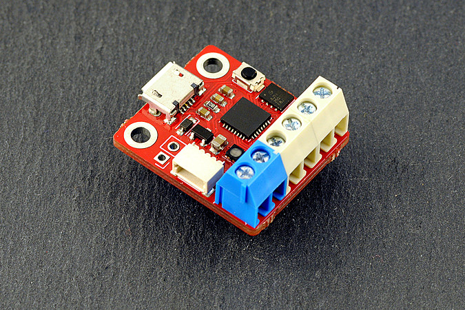
FIDI is a small development board running Adafruit's CircuitPython, featuring 6 terminal block connectors and a qwiic connector, designed for fast prototyping. It runs on the ATSAMD21 microcontroller, a 32-bit Arm Cortex M0+ clocked at 48Mhz, as found on many popular Arduino-compatible boards.
Though FIDI only features 6 GPIOs, they can be configured as digital or analog IOs, SPI, I2C, UART, or a combination thereof. Four of those GPIOs are available through terminal block connectors, allowing connections with a simple screwdriver. The two remaining GPIOs are available on a four-pin JST-SH connector, in an arrangement that is fully compatible with Sparkfun's qwiic connector system (also called STEMMA QT by Adafruit). This allows you to quickly test sensors and other circuits without any soldering.
Thanks to CircuitPython, writing code for FIDI is super simple. Once connected to a computer with a simple USB micro connector, FIDI shows up as a USB drive where you can drag-and-drop or edit your python code.
FIDI is open-source hardware. In fact, it's a derivative of Arturo182's excellent SERPENTE. The main difference between SERPENTE and FIDI is the connectivity, with FIDI featuring Micro USB, 3.5mm terminal blocks, and JST connectors. On the software side, FIDI is 100% compatible with SERPENTE. Please note that OMZLO is not affiliated with SERPENTE or its author Arturo182.
Technical details
The main technical features of the board are:
- A small size: it measures 25.4mm x 22mm (1" x 0.86")
- Microchip ATSAMD21E18A 32-bit Arm Cortex M0+ running at 48MHz, with 256KB flash, and 32KB RAM
- 4MB flash for CircuitPython code and other files,
- Six GPIOs, featuring SPI, I2C, UART, Digital/Analog IO, PWM, ...
- 3.5mm terminal block connectors and one 4 pin JST-SH connector (qwiic).
- 3.3V logic level, maximum 200mA
- USB micro connection to PC
- User-controlled RGB LED
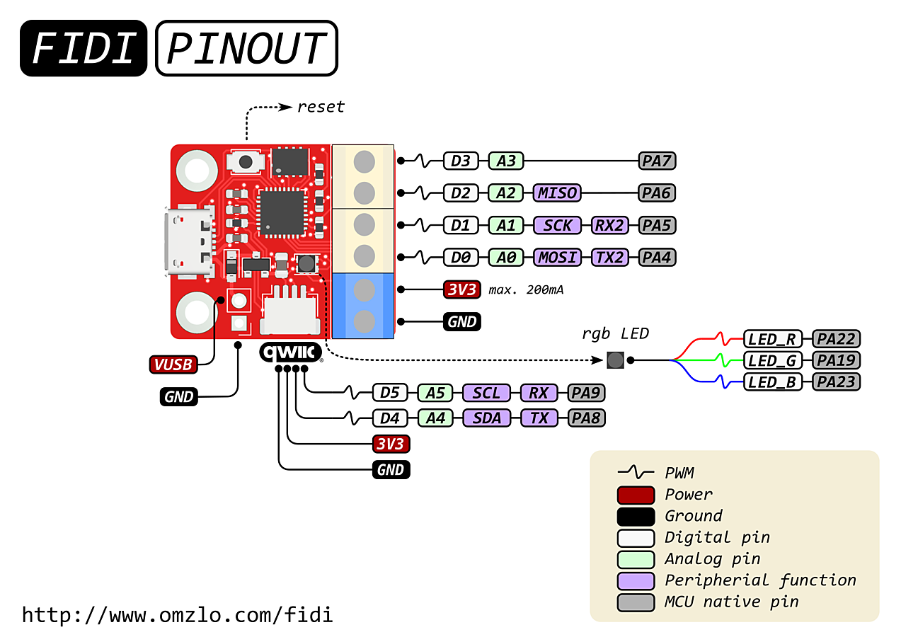
The pinout of the board is shown below.
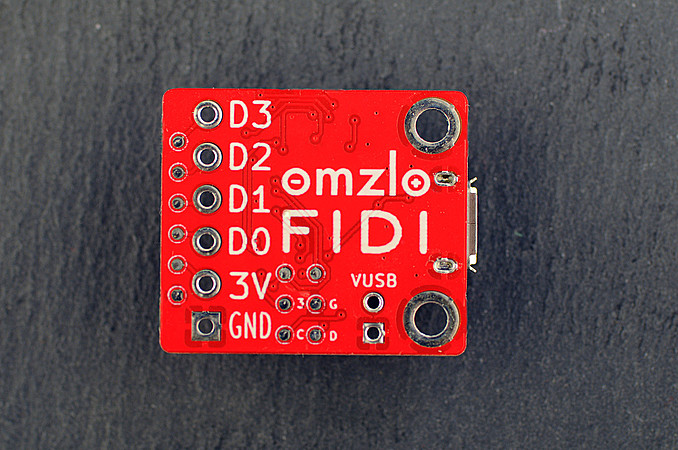
The back of the board is shown here.
The main differences between FIDI and SERPENTE are summarized in the table below.
| FIDI | SERPENTE | |
|---|---|---|
| Maximum LDO current | 200mA | 250mA |
| Connectors | Terminal blocks, Qwiic | Pin headers |
| Castellated edges | No | Yes |
| USB connection. | Micro-USB | USB-C or USB-A |
SERPENTE can be simultaneously powered by USB and an external power source. However, FIDI should be disconnected from USB when powered by an external source.
Using FIDI
Connecting to a computer
When plugged into a computer, FIDI becomes accessible through two USB interfaces:
- As a USB flash drive of 4MB, named
CIRCUITPY. - As a USB serial interface (e.g.
/dev/tty.usbmodem1411401on Mac OS).
Programming the FIDI is a simple as editing the file called code.py on the USB drive.
The serial interface allows access to debug information and an interactive python shell.
More details can be found in Adafruit's excellent CircuitPython guide.
Working with CicuitPython
The SERPENTE documentation already describes how to configure the various peripherals available on the board through the GPIOs.
The python board definition provides the following pins:
- Analog:
A0,A1,A2,A3,A4,A5 - Digital:
D0,D1,D2,D3,D4,D5 - LEDs:
LED_B,LED_G,LED_R - SPI:
MISO,MOSI,SCK - USART:
RX,TX,RX2,TX2 - I2C:
SCL,SDA
Since FIDI has only 6 GPIOs, many of these pin definitions are equivalent. For example, board.D5 is the same as board.SCL.
Blinking an LED
FIDI comes with an RGB LED, where each color component (Red, Green, Blue) is connected to a distinct pin. The 3 LED pins use reverse logic, where HIGH clears an LED, and LOW lights it up. Blinking the green LED is as simple as running the following code:
import time
import board
from digitalio import DigitalInOut, Direction

# Classic blinky

led = DigitalInOut(board.LED_G)
led.direction = Direction.OUTPUT

while True:
    led.value = False # On
    time.sleep(0.5)
    led.value = True # Off
    time.sleep(0.5)
All pins on the FIDI can do PWM, so the above example can be easily modified to do pulsating LEDs, using the CircuitPython pulseio library.
Analog read
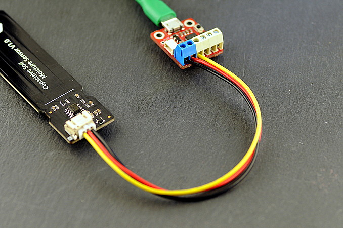
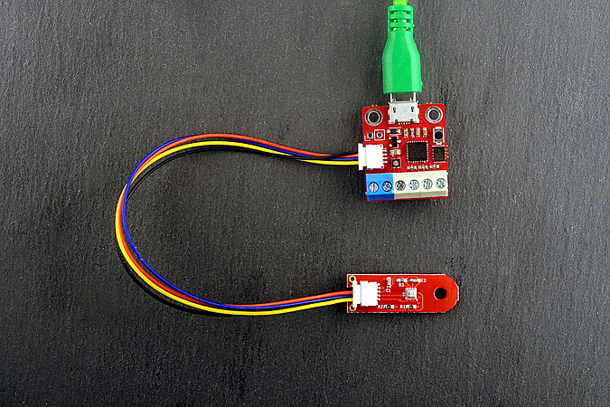
Consider a simple capacitive moisture sensor that require 3 wires for connection: 3.3V, GND and an analog output to read the soil moisture level.
We will connect the analog output of the sensor to pin A0 of the FIDI. The 3.3V and GND will be supplied by the FIDI on the blue terminal blocks, as shown here.
The python code necessary to read the raw analog output of the sensor is very simple.
import time
import board
from analogio import AnalogIn

analog_in = AnalogIn(board.A0)

while True:
    print(analog_in.value,)
    time.sleep(0.5)
The output of this program is visible on the USB serial terminal exposed by the board.
Connecting to an I2C BME280 sensor
Let's look at an I2C sensor with the popular qwiic connector like our own BME280 atmospheric sensor breakout. You can plug it directly into the FIDI and quickly test it.
By default, most CircuitPython boards like FIDI don't come with drivers for specific sensors like the BME280. We could take the BME280 datasheet and write I2C code in Python to fetch data from the sensor. But we don't need to do that: Adafruit provides a bundle of libraries for MicroPython that contains a ton of drivers and code to interface with electronics, including the BME280.
Once we get the bundle and unzip it, we need need to do the following:
- Create a
libdirectory on the CIRCUITPY flash drive if it does not exist. - Copy
adafruit_bme280.mpyandadafruit_bus_deviceinto thelibdirectory.
Now we can retrieve data from the sensor with the following code:
import board
import time
import adafruit_bme280

i2c = board.I2C()
bme280 = adafruit_bme280.Adafruit_BME280_I2C(i2c)

while True:
    print("\n")
    print("Temperature: %0.1f C" % bme280.temperature)
    print("Humidity: %0.1f %%" % bme280.humidity)
    print("Pressure: %0.1f hPa" % bme280.pressure)
    time.sleep(2)
Again, the output of this program is visible on the serial terminal, showing temperature, humidity, and pressure.
Adafruit's bundle of libraries for MicroPython is truly an amazing resource for quick prototyping.
What's included
The FIDI board is provided fully assembled except for the 3 terminal blocks that need to be soldered to the board, as shown in the picture below.
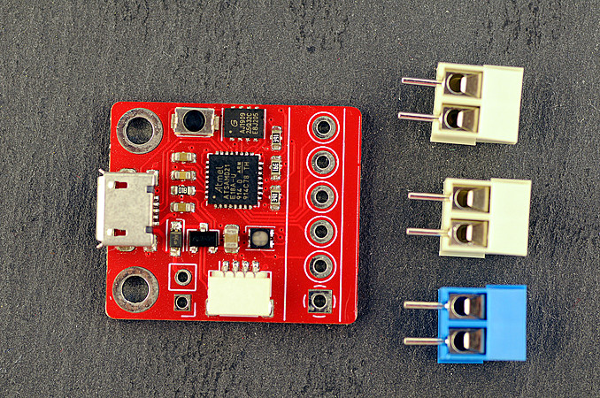
The 3 terminal blocks should be first connected to each other, using the tiny slots on their sides. The blue terminal block should be positioned so as to fit on the bottom lower pins of the board, next to the qwiic connector, as shown on the various pictures above. Once they are connected and perfectly aligned, the terminal blocks can be soldered to the board.
FIDI comes preloaded with CircuitPython 5.0.0, and the uf2 bootloader.
Resources
You can buy a FIDI on Tindie now
Design files:
Links:
- Adafruit CircuitPython guide.
- SERPENTE the board from which FIDI is derived.
Comments
I really like the FIDI! It’s small size and processing power are a great combination for prototyping.
I made a blog/GitHub entry based on how I used it. Let me know if you want the link (I would post it here, however links are disabled)
Lief
Lief, over 4 years ago1 comment triggered our SPAM filter and will be reviewed before publication.
Leave a comment