
Introduction
Are you an 8-bit or a 32-bit programmer?
At OMZLO, we have been mainly focussing our development efforts on newer 32-bit Arm-Cortex chips (STM32 and SAMD), which typically offer more RAM, more speed, more peripherals, at a similar or lower price-point than older 8-bit MCUs. But 8-bit MCUs are far from dead. Microchip has notably released a new series of chips, collectively branded as the "tinyAVR 0-series", which offer more modern peripherals than the older AVR chips at a very competitive price point. They seem like the perfect candidate for simple products that don't need all the features and fine-tuning capabilities of the newer 32-bit MCUs. 8-bit MCUs are also substantially simpler to program, which translates into faster development time.
Thanks to the success of the Arduino UNO, there are tons of tutorials online that explain how to program 8-bit Atmega328 microcontrollers and their cousins like the Attiny85 using direct register access, without the Arduino language or any vendor IDE such as Atmel Studio. Just google "atmega328 blinky". All you need is an AVR C-compiler, a text editor, avrdude, and an AVR programmer. Some resources even show how to also build the electronics needed to get a basic atmega328 running on a breadboard. However, it's hard to find the same information for these newer "tinyAVR 0" chips.
Of course, Microchip offers all the tools necessary to program these newer "TinyAVR" MCUs with their windows-only IDE. There are also "Arduino cores" for some of these newer "TinyAVR" MCUs that let you program them with the Arduino IDE. But again, if you like to write code for MCUs in "baremetal" style, with your favorite text editor, a makefile, and a c-compiler, there are few resources available online.
In this blog post, we will describe how to program a blinky firmware on an Attiny406, from the ground up, using the simplest tools. Most of the things described here can be easily transposed to other TinyAVR MCUs. Our approach is generally guided toward macOS or Linux users, but should also be applicable in an MS-Windows environment with a few minor changes.
Hardware
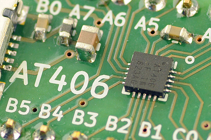
We decided to play with the Attiny406, with a view of using it in the future to replace the Attiny45 we currently use on the PiWatcher, our Raspberry-Pi watchdog. The Attiny406 has 4K of flash space, 256 bytes of RAM, and can run at 20Mhz without an external clock source.
One of the most important differences between the new TinyAVR MCUs and the older classic AVR MCU like the Attiny85 is that the newer chips use a different programming protocol called UPDI, which requires only 3 pins, as opposed to the 6-pin ISP on the classic AVRs.
A little research shows that programming TinyAVRs with UPDI can be achieved with a simple USB-to-serial cable and a resistor, thanks to a python tool called pyupdi, which suggests the following connection diagram for firmware upload:
                        Vcc                     Vcc
                        +-+                     +-+
                         |                       |
 +---------------------+ |                       | +--------------------+
 | Serial port         +-+                       +-+  AVR device        |
 |                     |      +----------+         |                    |
 |                  TX +------+   4k7    +---------+ UPDI               |
 |                     |      +----------+    |    |                    |
 |                     |                      |    |                    |
 |                  RX +----------------------+    |                    |
 |                     |                           |                    |
 |                     +--+                     +--+                    |
 +---------------------+  |                     |  +--------------------+
                         +-+                   +-+
                         GND                   GND
shematic
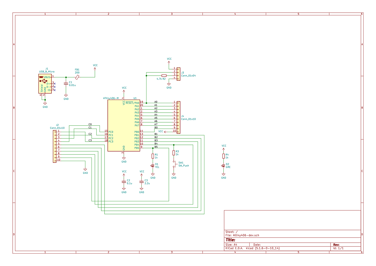
We created a minimalistic breakout board for the Attiny406. The board can be powered by 5V through USB or a lower 3.3V through dedicated VCC/GND pins. An LED and a button were also fitted on the board. For testing purposes, we decided to embed the 4.7K resistor needed for the UPDI programming directly in the hardware (i.e. resistor R2). This gives us the following schematic:
Board
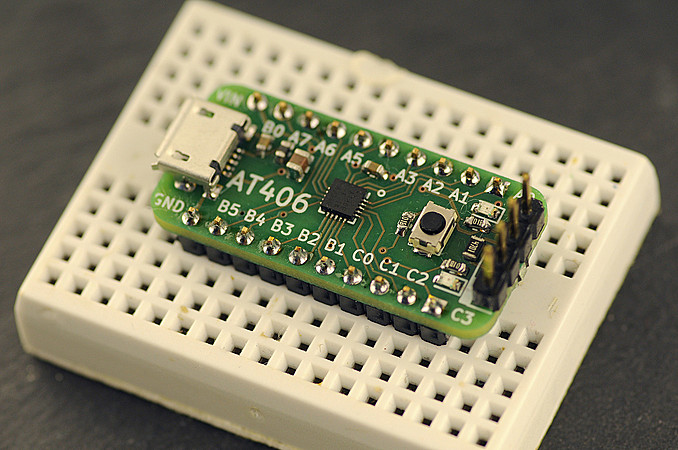
The resulting breakout board is tiny and fits conveniently on a small breadboard. The design files are shared on aisler.net.
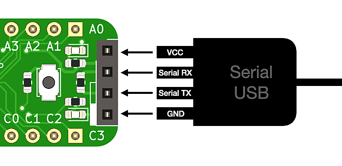
Programming the Attiny406 on the board with a USB-serial cable is done by connecting the headers on the board edge:
Software
pyudpi
We installed pyupdi following the instructions provided on their webpage.
We connected our USB-Serial cable to the board with the 4 dedicated UPDI pins available on the board. Our USB-Serial converter shows up as the file /dev/tty.usbserial-FTF5HUAV on a MacOS system.
To test that the programmer recognizes the Attiny406, you can issue a command similar to the following, adapting the path for the USB-serial converter to your setup:
pyupdi -d tiny406 -c /dev/tty.usbserial-FTF5HUAV -i
This should result in the following output if all goes well:
Device info: {'family': 'tinyAVR', 'nvm': 'P:0', 'ocd': 'D:0', 'osc': '3', 'device_id': '1E9225', 'device_rev': '0.1'}
The C compiler
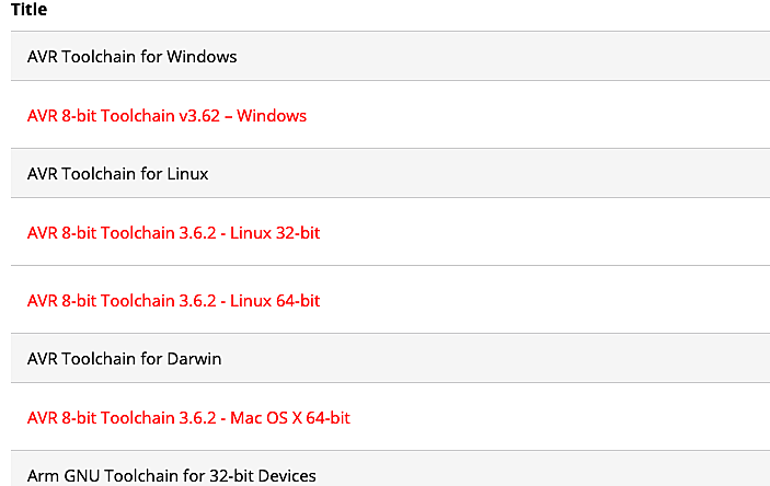
The typical avr-gcc available on macOS with homebrew did not seem to recognize the Attiny406 as a compiler target, so we went off to install the avr-gcc compiler provided by Microchip, which is available here. Downloading the compiler requires you to create an account on the Microchip website, which is a bit annoying.
Once downloaded, we extracted the provided archive in a dedicated directory. The bin directory in the archive should be added to the PATH variable to make your life easier. Assuming the downloaded compiler is stored in the directory $HOME/Src/avr8-gnu-toolchain-darwin_x86_64, the PATH can be altered by adding the following line to your .bash_profile file:
export PATH=$PATH:$HOME/Src/avr8-gnu-toolchain-darwin_x86_64/bin/
Newer Attiny MCUs are not supported out of the box by the Microchip avc-gcc compiler. You need to download a dedicated Attiny Device Pack from their website, as shown below:
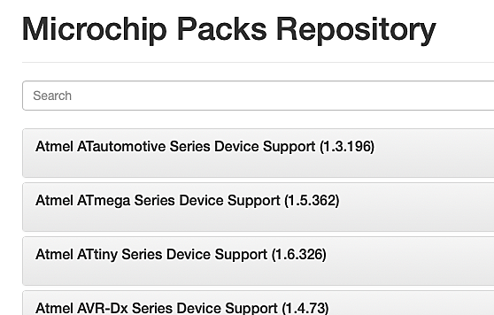
The resulting downloaded Device Pack is named Atmel.ATtiny_DFP.1.6.326.atpack (or similar depending on versioning). Though the extension is .atpack, the file is actually a zip archive. We changed the extension to .zip and extracted the package in the directory $HOME/Src/Atmel.ATtiny_DFP.1.6.326 next to the compiler files.
C program
We created the following program that blinks the LED on pin PB5 of our Attiny board at a frequency of 1Hz.
#include <avr/io.h>
#include <util/delay.h>

int main() {
    _PROTECTED_WRITE(CLKCTRL.MCLKCTRLB, 0); // set to 20Mhz (assuming fuse 0x02 is set to 2)

    PORTB.DIRSET = (1<<5);
    for (;;) {
        PORTB.OUTSET = (1<<5);
        _delay_ms(500);
        PORTB.OUTCLR = (1<<5);
        _delay_ms(500);
    }
}
The code looks very similar to what you would see on a classic AVR "blinky" program. One visible change is the use of structures to access various registers of the MCU: e.g instead of setting bits in PORTB, you access PORTB.DIRSET.
The other visible change is the clock setup code _PROTECTED_WRITE(CLKCTRL.MCLKCTRLB, 0). Out of the box, at reset, the Attiny406 runs at 3.33Mhz, which corresponds to a base frequency of 20Mhz with a 6x clock divider applied. To enable the full 20Mhz speed, the register CLKCTRL.MCLKCTRLB is cleared. Because this register needs to be protected against accidental changes, the Attiny406 requires a specific programming sequence to modify it. Fortunately, this is natively offered by the macro _PROTECTED_WRITE. More details are available in the Attiny406 datasheet.
In comparison with an STM32 or a SAMD21, the code is blissfully simple.
Makefile
We assume the following directory structure where:
Src/Atmel.ATtiny_DFP.1.6.326/is the location of the Microchip Device PackSrc/attiny406-test/is the directory where the code above is stored in a file calledmain.c
Compiling the code can be done by issuing the following command within attiny406-test/ directory,:
avr-gcc -mmcu=attiny406 -B ../Atmel.ATtiny_DFP.1.6.326/gcc/dev/attiny406/ -O3 -I ../Atmel.ATtiny_DFP.1.6.326/include/ -DF_CPU=20000000L -o attiny406-test.elf main.c
An -O optimization flag is required to make the _delay_ms() function calls work successfully, as well as defining the variable F_CPU to reflect the expected chip clock speed. The rest of the parameters provide the location of the Attiny406 device-specific files we previously extracted from the Device Pack.
Uploading the firmware to the MCU requires a conversion to the intel HEX format and a call to the pyupdi tool. To address all these steps, we created a simple Makefile.
OBJS=main.o
ELF=$(notdir $(CURDIR)).elf
HEX=$(notdir $(CURDIR)).hex
F_CPU=20000000L


CFLAGS=-mmcu=attiny406 -B ../Atmel.ATtiny_DFP.1.6.326/gcc/dev/attiny406/ -O3
CFLAGS+=-I ../Atmel.ATtiny_DFP.1.6.326/include/ -DF_CPU=$(F_CPU)
LDFLAGS=-mmcu=attiny406 -B ../Atmel.ATtiny_DFP.1.6.326/gcc/dev/attiny406/
CC=avr-gcc
LD=avr-gcc

all:    $(HEX)

$(ELF): $(OBJS)
                $(LD) $(LDFLAGS) -o $@ $(OBJS) $(LDLIBS)

$(HEX): $(ELF)
                avr-objcopy -O ihex -R .eeprom $< $@

flash:  $(HEX)
                pyupdi -d tiny406 -c /dev/tty.usbserial-FTF5HUAV -f attiny406-test.hex

read-fuses:
                pyupdi -d tiny406 -c /dev/tty.usbserial-FTF5HUAV -fr

clean:
                rm -rf $(OBJS) $(ELF) $(HEX)
To compile the code, we simply type make. Uploading is done with make flash. This Makefile can be further enhanced as needed.
Conclusion
With the right tools, baremetal programming on the new TinyAVR MCUs is as simple as on its older AVR cousins.
If you have programming tips for the AVRTiny, please share them with us on on Twitter or in the comments below.
Edit:
- Paul Evans provides some extra info about (building for new ATmega 0-series chips on Debian)[https://leonerds-code.blogspot.com/2020/11/building-for-new-atmega-0-series-chips.html]
Comments
Hi,
It's great that someone else is doing things with these MCUs, I've used them in some recent projects and they're great, I'm using the attiny1617 in my main projects.
I wrote a script to automate setup of the toolchain here:
https://github.com/MarkR42/robotbits/tree/master/avr_toolchain
Which I think supports the 406. I haven't tried it on a Mac, the main target is Linux.
I'm pleased that I don't need to use any fancy libraries (except the avr C library and their very minimal runtime / startup code) and it's all simple enough that I can disassemble my firmware and see exactly what's happening.
Mark Robson, almost 6 years agoHow about send $ and we send you a kit?
I am an old hand at bare level programming :).
John
John, almost 6 years agoHi, Great tutorial, I have a few Atmega4809 in a box, waiting to play. They use the same UPDI interface, have you tried the same toolchain and Microchip tools with this MCU?
Best regards,
Javier.
Javier Cano, almost 6 years agoGreat tutorial, and I like the idea of baremetal programing. Thank you for sharing! I decided to design a variant board that would be easier for me to handsolder and be friendly with my FTDI cables. I posted the design files and BOM on github profile DCelectronics, in the repository ATtiny406_Board. I hope more people get interested in developing with AT406 and contribute to the open source community.
DCelectronics, almost 6 years agoI'd buy a board, any chance you'll be selling?
graeme, almost 6 years agoHow do you handle +12V pulse for UPDI entry?
UPDI expert, over 5 years ago@UPDI expert: By default, you don't need a +12V pulse for UPDI programming. You only need that to unlock the UPDI pin in case you reconfigured the pin into a RESET or GPIO pin.
Omzlo, over 5 years agoFunny that "UPDI expert" does not know that the +12V is not necessary by default.
UPDI rookie, over 4 years agoFunny that "UPDI expert" does not know that the +12V is not necessary by default.
UPDI rookie, over 4 years agoIf I wanted to use the UPDI pin as RESET, does it matter how long after the +12V pulse i start the programming sequence described in here?
UPDI enthusiast, over 4 years ago390 comments triggered our SPAM filter and will be reviewed before publication.
Leave a comment