In a previous article, I described the construction of a HAT that enables you to power a Raspberry Pi with voltage inputs ranging from 7V to 28V, as provided by a car battery for example. This HAT was an accidental byproduct of the Omzlo PiMaster HAT, which typically provides 12V or 24V to a network of IoT modules connected through CAN bus, and powers a Raspberry Pi using a similar circuit. Some readers asked us if we were selling this HAT, so we started looking at producing a small batch.
A cheaper circuit
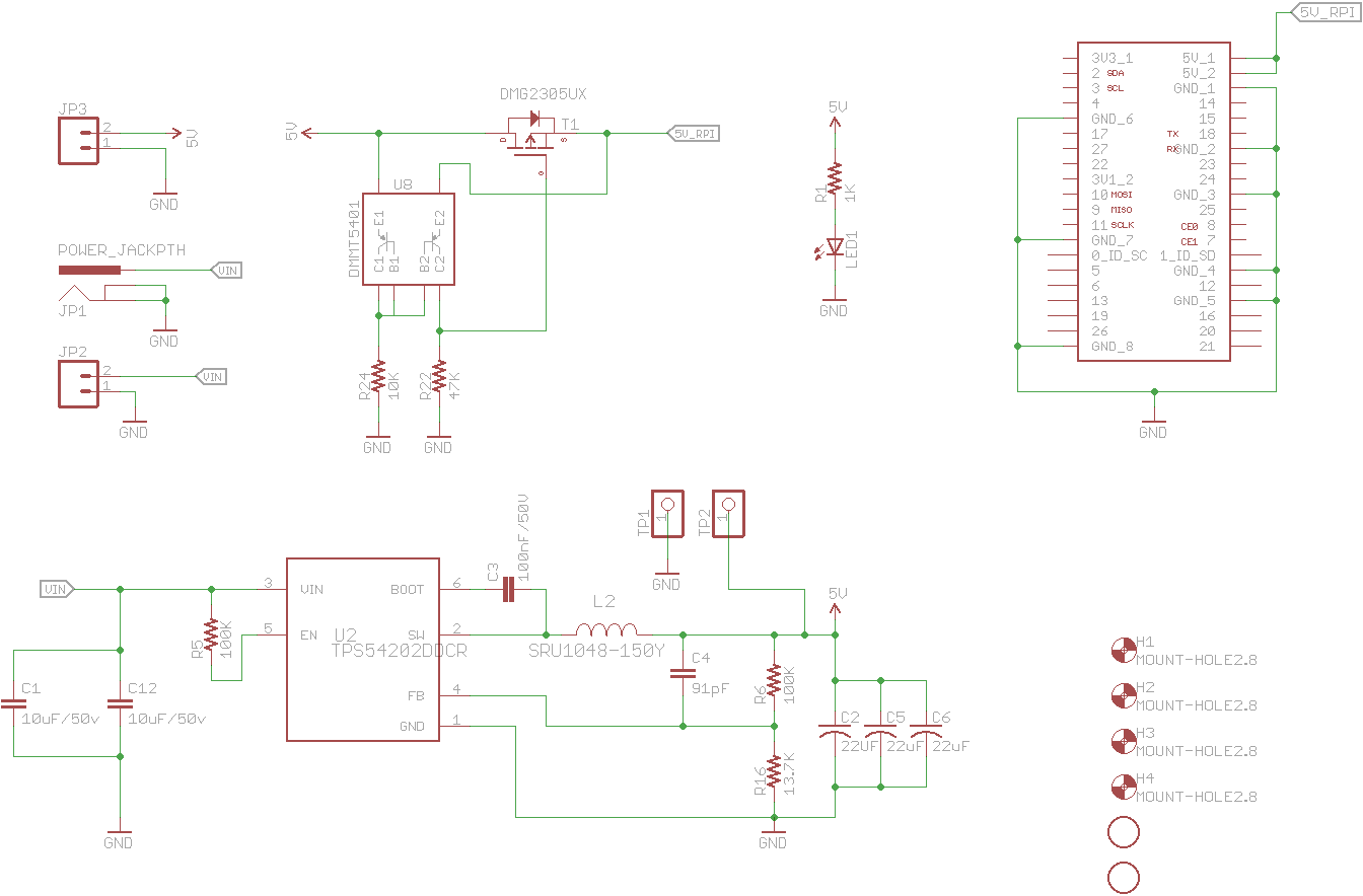
The circuit is a simple buck switching regulator based on the Texas Instrument TPS54202, which steps down the input voltage to 5V for the Raspberry Pi. As a protection, the 5V output goes through an "ideal" diode following the recommendation of the Raspberry Pi Foundation.
It turns out that the 330uF polymer aluminum electrolytic capacitor I used in the first design is quite expensive (2 to 3 euros) and annoying to solder. So I went back to Texas Instrument's online power supply design tool, WEBENCH, and found an alternative approach that uses three 22uF ceramic capacitors instead, as shown on the schematic below:
The resulting circuit exhibits a voltage ripple of approximately 20mV pp. This is similar to the original circuit, but it has a more pronounced "sawtooth" wave shape on the oscilloscope. It is perfectly fine for a Raspberry Pi.
Open hardware: design files
The final soldered PCB looks like this:

You can find the EagleCAD files here and the BOM in the table below.
| Qty | Value | Device | Parts | Description |
|---|---|---|---|---|
| 1 | LED 0805 | LED1 | LED | |
| 2 | 100K | R0603 | R5, R6 | Resistor |
| 1 | 100nF/50V | CAP0603 | C3 | Capacitor |
| 1 | 10K | R0805 | R24 | Resistor |
| 2 | 10uF/50v | CAP1206 | C1, C12 | Capacitor |
| 1 | 13.7K | R0603 | R16 | Resistor |
| 1 | 1K | R0805 | R1 | Resistor |
| 3 | 22uF | CAP1210 | C2, C5, C6 | Capacitor |
| 1 | 47K | R0805 | R22 | Resistor |
| 1 | 91pF | CAP0603 | C4 | Capacitor |
| 1 | DMG2305UX | P-CH-MOSFET | T1 | P-Channel MOSFET Mode Field Effect Transistor |
| 1 | DMMT5401 | DMMT5401 | U8 | Matched BJT pair |
| 1 | POWER_JACKPTH | POWER_JACK | JP1 | Power Jack |
| 1 | SRU1048-150Y | SRU1048-150Y | L2 | Inductor |
| 1 | TPS54202DDCR | TPS54202DDCR | U2 | Buck converter |
Conclusion
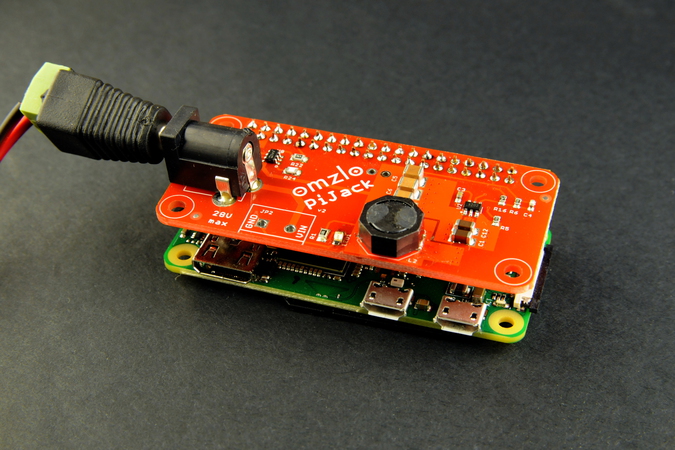
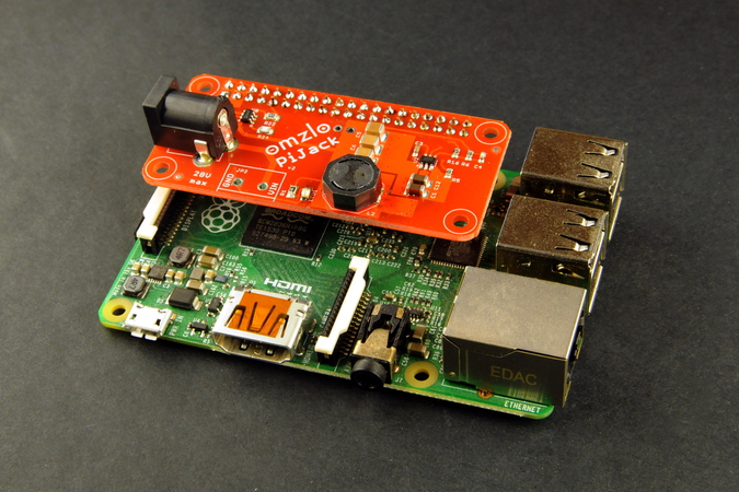
As shown in the very first picture of this article, this HAT was designed to fit on top of a Raspberry Pi Zero. However, it works just as well on any Raspberry Pi with a 40pin GPIO header, like the Raspberry Pi 3, as illustrated below.

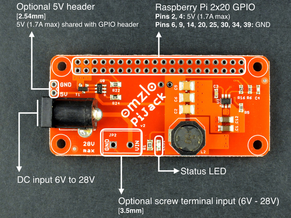
This circuit was successfully tested to power the Raspberry Pi 2, Pi 3 and Pi Zero W. It is theoretically comfortable providing up to 1.7A 2.5A, with inputs ranging from 6V to 28V (the first version of this article erroneously gave a lower range of 7V).
If you don't feel like building your own, we have produced a first batch of 30 PiPower HATs that are now for sale on Tindie!
If you liked this article, follow us on twitter or on our facebook page.
UPDATE: As of May 2020, the Texas Instrument TPS54202 has been replaced with a TPS54302, increasing the current output limit from 1.7A to 2.5A in order to work with the Raspberry Pi 4.
UPDATE 2: As of March 2021, the PiJack has been redesigned with a Texas Instrument LMR33630, increasing the current output limit to 3A, and the input range to 36V (32V max recommended).


Comments
Dear Sirs, is this PI JACK board protected from reversed power inpurt polarity? Many thanks in advance.
Best regards and happy new year.
Simone
Simone Pariani, about 4 years agoDear Sirs, is this PI JACK board protected from reversed power inpurt polarity? Many thanks in advance.
Best regards and happy new year.
Simone
Simone Pariani, about 4 years agoWherry to buy this board? I am interesten in 2 complete solderen boards.
Benthouse, over 2 years agoGreetings,
Looking for ways to streamline operations, enhance efficiency, and cut costs by up to 50% through outsourcing?
We have two state-of-the-art tech centers with over 1,000 agent positions available for:
- Multi-channel Customer Support & Help Desk via voice, text, chat, and email.
- Lead Recovery: Turn abandoned e-commerce leads into new sales.
- Professional Virtual Assistants for finance, legal, healthcare, and more.
- Market Outreach to enhance lead generation and schedule software demos.
Avoid hassles, let us work with you to cut costs, expand and help simplify operations!
Book your free consultation now: http://bit.ly/ABC-book-a-meeting
Warm regards,
C.J. Ebanks
ABC Services Webpage: http://bit.ly/ABC-book-a-meeting 1-866-904-6927
Should you wish to stop getting subsequent correspondence from us, simply visit and fill the form at https://bit.ly/removeuspls Ackerweg 86, Stapfing, NY, USA, 5233
CJ Ebanks, about 1 year agoHi,
Hair loss doesn’t have to define you. Whether you’re noticing thinning, a receding hairline, or patchy areas, there’s a proven solution designed for both men and women to restore your hair and confidence.
This advanced hair regrowth system: - Includes an FDA-approved ingredient to reactivate dormant hair follicles. - Combines essential nutrients to support regrowth from the inside out. - Is tailored for men and women to address specific needs. - Is simple, discreet, and delivered directly to your door.
Take control of your hair loss with a system designed to promote natural, thicker hair regrowth without hassle.
++ Learn more and take the first step today: For Men https://bit.ly/PHR4Men For Ladies https://bit.ly/PHRLadies
Your journey to healthier, fuller hair starts here.
The truth about hair loss over 60 million men will suffer from hereditary hair loss by the time they are 40 years old.
FACT: Hereditary hair loss can come from the father’s side or the mother’s side. FACT: PHR contains the only FDA approved ingredient to fight hair loss and thinning hair in over 96% of men.
How does PHR provide such amazing results? As we age, our bodies stop producing the vital hormones that promote proper hair health and growth. With PHR' advanced blend of natural & powerful ingredients, the body can actually start to refill these hormones, sending the necessary vitamins and nutrients directly to the scalp and newly formed hair follicles.
PHR Women is a scientifically formulated hair regrowth treatment for women. It contains clinically proven ingredients that promote thicker, healthier hair. With consistent use, it can help reduce hair loss and stimulate new hair growth, giving you fuller and more luscious locks.
Hair Loss, Damaged Hair, Thinning Roots, and Weak Follicles are all symptoms of completely different causes.So why would any company focus on just one thing, when we need to fix all FOUR to get truly beautiful, full, and strong hair? Our unique patented formula does just that.
Don't hesitate, your satisfaction is guaranteed!
If at any point you decide not to receive updates from us, kindly write back to this communication with the words "No Thank You". 48 Boulevard De Prague, Elbridge, NY, USA, 30000
Violet Valdez, about 1 year agoLeave a comment